Electric vehicle

a technology of electric vehicles and protruding portions, applied in the direction of cycle equipment, electrochemical generators, cycles, etc., can solve the problems of increasing the length of respective wires connected to the on-board batteries, the need for complicated wire routing, and the need for plural stays, so as to increase the cooling effect, the effect of increasing the heat release effect of the surface of the protruding portion, and simple structur

Active Publication Date: 2015-02-17
HONDA MOTOR CO LTD
View PDF42 Cites 1 Cited by
  • Summary
  • Abstract
  • Description
  • Claims
  • Application Information

AI Technical Summary

Benefits of technology

[0006]Accordingly, an electric vehicle is provided with a simple structure allowing effective cooling of on-board batteries that are collectively disposed within a swing arm.
[0023]According to the eighth feature, within the swing arm, there are housed at least the electric motor, the batteries, and a substrate having a drive circuit of the electric motor and a charging circuit for the batteries. Therefore, the components accompanied by extreme heat generation in the electric vehicle are housed within the swing arm, so that all these heating elements can be cooled by the cooling structures provided on the swing arm. Consequently, since it becomes unnecessary to provide cooling structures on the vehicle body, the vehicle body structure can be simplified.

Problems solved by technology

However, in the technology disclosed in JP-B No. 3493666, since the on-board batteries are disposed at the dispersed locations of the vehicle body, there have been problems of increases in length of respective wires connected to the on-board batteries, the need for a complicated routing of the wires, and the need for plural stays for fixing the on-board batteries to the vehicle body.
On the other hand, if the on-board batteries are collectively disposed within the swing arm in order to address these problems, the on-board batteries generating heat during traveling are disposed close to one another, leading to difficulty in cooling.
For this reason, there has been a problem in that the need for providing an electric fan or the like for facilitating cooling in the swing arm arises.

Method used


Image

  • Electric vehicle
  • Electric vehicle
  • Electric vehicle

Examples


Embodiment Construction

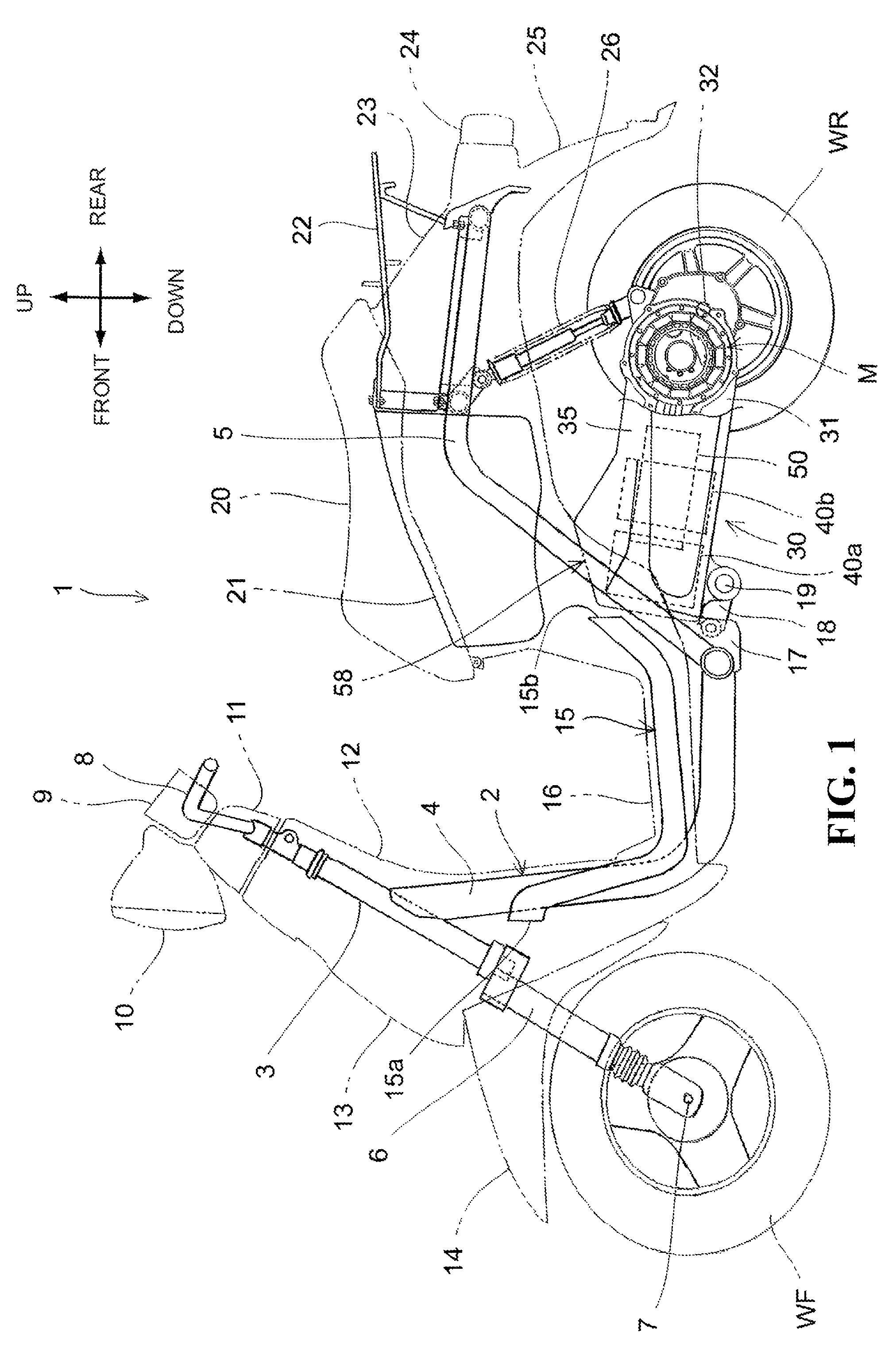
[0033]Hereinafter, preferred embodiments of the present invention will be described in detail with reference to the accompanying drawings. FIG. 1 is a side view of an electric vehicle 1 according to one embodiment. The electric vehicle 1 is a saddle-ride type two-wheeled vehicle of scooter type having a low floor 16, in which a rear wheel WR is driven by an electric motor M housed in a swing arm (unit swing) 30. A head pipe 3 for rotatably journaling a stem shaft (not shown) is connected to a front portion of a body frame 2. A steering handlebar 8 covered with a handlebar cover 11 is connected to an upper portion of the stem shaft. On the other hand, a pair of left and right front forks 6 for turnably journaling a front wheel WF through an axle 7 is connected to a lower portion of the stem shaft.

[0034]The body frame 2 includes a main pipe 4 extending downward from a rear portion of the head pipe 3, and a rear frame 5 coupled to a rear end of the main pipe 4 and extending upward towa...


PUM


Abstract

An electric vehicle has simple structure allowing effective cooling of on-board batteries collectively disposed within a swing arm. The electric vehicle includes a swing arm that houses an electric motor that is swingably mounted to a vehicle body and drives a drive wheel WR, and batteries of a substantially rectangular parallelepiped. A wide case portion that houses the batteries is formed at a position toward a pivot shaft of the swing arm. Also, a protruding portion for forming an air reservoir space above the batteries is formed at a roof portion of the wide case portion. The batteries are disposed side by side in a front-rear direction of the vehicle body. The protruding portion, in a side view of the vehicle body, is substantially convex protruding upward across the batteries.

Description

CROSS REFERENCE TO RELATED APPLICATIONS[0001]The present application claims priority under 35 U.S. C §119 to Japanese Patent Application No. 2011-004877 filed Jan. 13, 2011 entitled “Electric Vehicle.” The contents of this application are incorporated by reference in their entirety.TECHNICAL FIELD[0002]The application relates to an electric vehicle, and more particularly, to an electric vehicle in which the electric power is supplied to an electric motor from on-board batteries to rotate a drive wheel by the driving force of the electric power, thereby traveling.BACKGROUND OF THE INVENTION[0003]In the past, there has been known an electric vehicle in which the electric power is supplied to an electric motor from on-board batteries to rotate a drive wheel by the driving force of the electric power, thereby traveling.[0004]JP-B No. 3493666 discloses a saddle-ride type two-wheeled electric vehicle of scooter type having a structure in which an electric motor is housed within a swing ar...

Claims


Application Information

Patent Timeline
Patent Type & Authority Patents(United States)
IPC IPC(8): B60K1/00B60R16/04B62K11/10B60K1/04B62J9/00B62J99/00B62K25/20B62M7/12
CPCB62K11/10B60K1/04B62K2202/00B60Y2200/12Y02E60/10B62K2204/00B60R16/04H05K7/20H01M10/6551
Inventor HATANAKA, KAORUTANIGUCHI, YOICHIYONEHANA, ATSUSHI
Owner HONDA MOTOR CO LTD
Why Eureka
Try Eureka