Novel energy-saving fan

A new fan, fresh air technology, applied in the field of air purification, can solve the problems of energy waste, poor ventilation, low exchange efficiency, etc., to achieve the effect of improving the utilization rate of waste heat, eliminating dead ends of heat exchange, and reducing maintenance costs

Inactive Publication Date: 2016-03-02
BROAD A Q TECH
View PDF8 Cites 4 Cited by
  • Summary
  • Abstract
  • Description
  • Claims
  • Application Information

AI Technical Summary

Problems solved by technology

[0004] However, the existing fresh air fans have the following disadvantages: (1) The design of the heat convection structure of the heat exchanger is unreasonable, and there are defects such as insufficient heat exchange, short heat exchange time, insufficient use of waste heat, low exchange efficiency, and energy waste; (2) The internal structure design of the new fan is unreasonable, with large volume, large wind resistance and poor exhaust

Method used


Image

  • Novel energy-saving fan
  • Novel energy-saving fan
  • Novel energy-saving fan

Examples


Embodiment Construction

[0031] The detailed structure of the present invention will be further described below in conjunction with the accompanying drawings and specific embodiments.

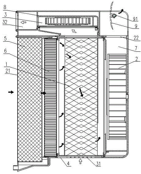
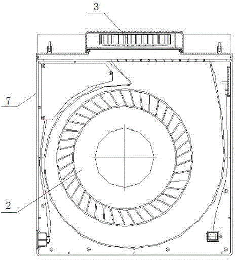
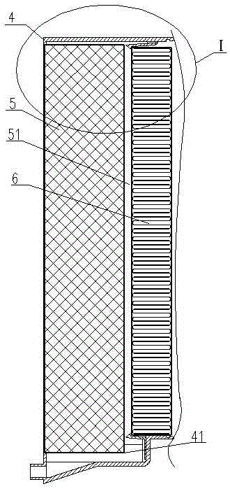
[0032] Such as figure 1 Shown: an energy-saving fresh fan, including a main casing 4, a filter, a heat exchanger 1 and a blower 2 are arranged in the main casing 4 along the air flow path in turn, and an exhaust fan 3 is also installed on the main casing 4, and the blower 2 and the The exhaust fan 3 is arranged vertically; the heat exchanger 1 adopts a counter-flow heat exchange structure, so that the fresh air of the blower 2 and the exhaust air of the exhaust fan 3 are vertically interlaced and sent out through the fresh air outlet 22 and the exhaust air outlet 32 ​​respectively.

[0033] Wherein, the filter and the heat exchanger 1 are installed in the main casing 4, the blower 2 is installed in the blower casing 7, the exhaust fan 3 is installed in the exhaust casing 8; the blower casing 7 is installed in the main ...


PUM


Abstract

A novel energy-saving fan comprises a main case; a filter, a heat exchanger and a supply fan are sequentially arranged in the main case along the air flowing path; an exhaust fan is also mounted on the main case; the supply fan is perpendicular to the exhaust fan; and the heat exchanger adopts a counter-current heat exchange structure, so that fresh air supplied by the supply fan is vertically staggered from exhaust air exhausted by the exhaust fan, and then the fresh air and the exhaust air are discharged from a fresh air outlet and an exhaust air outlet. The novel energy-saving fan has the advantages that on one hand, heat exchange dead angles are eliminated, and the waste heat utilization rate is improved, and the energy-saving effect is good; and on the other hand, the wind resistance is small, the air exhaust is smooth, and the filtering effect is good.

Description

technical field [0001] The invention relates to the technical field of air purification, in particular to an energy-saving fresh fan. Background technique [0002] With the development and expansion of industry, air pollution is becoming more and more serious, resulting in frequent occurrence of smog. Smog contains a large number of pollutants such as PM2.5 particles, which will seriously damage people's health and quality of life, especially for the elderly, children and patients with respiratory diseases. In addition, due to the rapid urbanization process in our country, the design and planning of many towns are unreasonable. There are industrial areas not far from residential areas, and even residential areas are surrounded by industrial areas; in this way, the exhaust gas in the factories is scattered by the wind. To the nearest residential area, people's living environment is very bad, if people live in such an environment for a long time, people's health will be serio...

Claims


Application Information

Patent Timeline
Patent Type & Authority Applications(China)
IPC IPC(8): F24F7/08F24F3/16F24F13/28
CPCF24F7/08F24F13/28F24F8/10F24F8/108
Inventor 张跃
Owner BROAD A Q TECH
Why Eureka
Try Eureka