Straw particle combustion furnace

A combustion furnace and particle technology, applied in the direction of air heaters, lighting and heating equipment, fluid heaters, etc., can solve the problems of indoor air pollution, complicated operation, etc., and achieve the effect of reasonable structure and convenient use

Inactive Publication Date: 2016-03-02
QINGDAO HICHANSE GRP
View PDF8 Cites 4 Cited by
  • Summary
  • Abstract
  • Description
  • Claims
  • Application Information

AI Technical Summary

Problems solved by technology

[0003] In order to solve the problem that the straw heating stove continuously adds fuel into the furnace manually, the operat

Method used


Image

  • Straw particle combustion furnace

Examples


Embodiment Construction

[0009] Below in conjunction with the embodiment of accompanying drawing, this implementation model is further described.

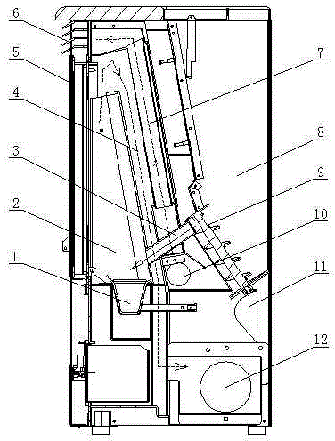
[0010] As shown in the figure, a furnace 2 is left in the front portion of the body of furnace 5 of the vertical cabinet shape, and the bottom of the furnace 2 is equipped with a combustion bucket 1, and a hot air port 6 is arranged on the front of the body of furnace 5 on the upper side of the furnace 2. A vertical flue 4 is left on the rear side, the upper end of the flue 4 communicates with the upper end of the furnace 2, the lower end of the flue 4 is equipped with a smoke exhaust machine 12, the rear side of the flue 4 is equipped with a blowing pipe 7, and the blowing pipe 7 The upper end of the blower pipe 7 communicates with the hot air outlet 6, and the lower end of the blower pipe 7 is equipped with a blower 10, and the rear side of the blower pipe 7 has a storage chamber 8, and a feed pipe 3 is arranged between the bottom of the storage chamber 8...


PUM


Abstract

A straw particle combustion furnace is characterized in that a hearth is reserved in the front portion in a vertical-cabinet-shaped furnace body, a combustion hopper is arranged at the lower portion of the hearth, a hot air port is formed in the front face of the part, on the upper side of the hearth, of the furnace body, and a vertical flue is reserved on the rear side of the hearth; the upper end of the flue is communicated with the upper end of the hearth, and a suction and discharge ventilator is arranged at the lower end of the flue; a blowing pipe is arranged on the rear side of the flue, the upper end of the blowing pipe is communicated with the hot air port, and a blower is assembled at the lower end of the blowing pipe; a storage chamber is reserved on the rear side of the blowing pipe, a feeding pipe is arranged between the lower portion of the storage chamber and the hearth, and a front end opening of the feeding pipe is located on the upper side of the combustion hopper; and a downwards-arranged screw rod is arranged at a rear end opening of the feeding pipe, and a feeding motor is arranged at the lower end of the screw rod. The straw particle combustion furnace solves the problems that according to a straw heating stove, fuel is constantly added in a hearth manually, operation is complex, and the indoor air is polluted, and is an ideal stove for combustion of straw particles.

Description

technical field [0001] The invention relates to the field of heating appliances in places such as homes, in particular to a stove using burning straw particles as raw materials. Background technique [0002] The traditional straw particle heating stoves all have a furnace opening in front of or above the furnace body, and straw particles are continuously added to the furnace manually. The disadvantage is that the operation is complicated, and when the furnace opening is opened, smoke overflows and pollutes the room. Air. Contents of the invention [0003] In order to solve the problem that the straw heating stove continuously adds fuel into the furnace manually, the operation is complicated, and the indoor air is polluted, the invention designs a straw particle burning stove with automatic feeding. [0004] The technical proposal of the present invention is a kind of stalk particle combustion furnace, which is special in that there is a furnace in the front part of the ca...

Claims


Application Information

Patent Timeline
IPC IPC(8): F24H3/08F24H9/00
Inventor 王洪源侯超
Owner QINGDAO HICHANSE GRP
Why Eureka
Try Eureka