Range-finding calibration tool and range-finding calibration method and device

A jig and calibration parameter technology, which is applied in the field of ranging calibration jigs and ranging calibration methods and devices, can solve problems such as inaccuracy, influence, and inaccurate ranging of ultrasonic sensors, and achieve the effect of improving the accuracy of ranging

Active Publication Date: 2016-03-02
GUANGDONG OPPO MOBILE TELECOMM CORP LTD
View PDF7 Cites 16 Cited by
  • Summary
  • Abstract
  • Description
  • Claims
  • Application Information

AI Technical Summary

Problems solved by technology

Since many applications of ultrasonic sensors on mobile terminals are based on the precise distance testing function of ultrasonic waves, if the distance tested by ultrasonic itself is incorrect or exceeds the allowable error range, it will inevitably affect the application of ultrasonic technology on mobile terminals. However, in the prior art, the ranging function...

Method used


Image

  • Range-finding calibration tool and range-finding calibration method and device
  • Range-finding calibration tool and range-finding calibration method and device
  • Range-finding calibration tool and range-finding calibration method and device

Examples


Embodiment 1

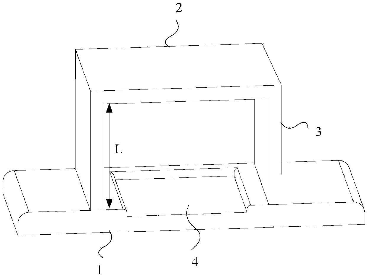
[0025] figure 1 A schematic structural diagram of the ranging calibration jig provided by Embodiment 1 of the present invention is given. Such as figure 1 As shown, the ranging calibration jig provided by Embodiment 1 of the present invention includes a placement platform 1 and a calibration substrate 2 located above the placement platform, and the placement platform 1 is parallel to the calibration substrate 2; the placement platform 1 is used for Place the mobile terminal to support the ultrasonic sensor of the mobile terminal to transmit ultrasonic waves to the calibration substrate 2; the calibration substrate 2 is used to reflect the received ultrasonic waves back to the ultrasonic sensor of the mobile terminal to support the The mobile terminal generates a test distance between the placement platform 1 and the calibration substrate 2, and generates distance measurement calibration parameters according to the test distance and a preset standard distance L.

[0026] The ...

Embodiment 2

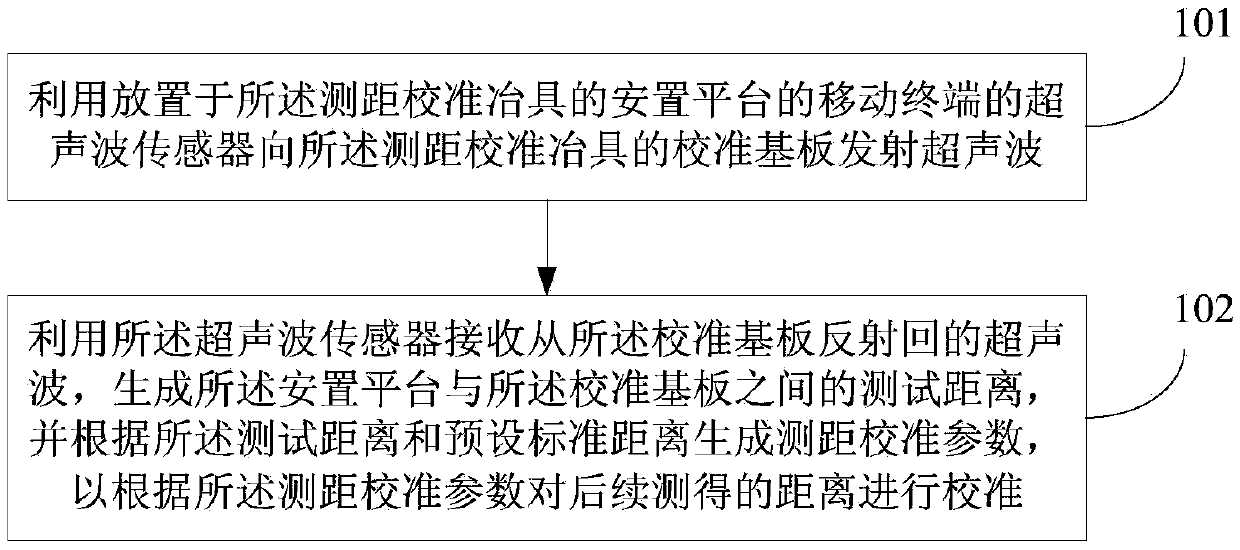
[0034] image 3 A flow chart of the distance measurement calibration method provided by Embodiment 2 of the present invention is given, and the method can be executed by a distance measurement calibration device. The device can be realized by software and / or hardware, and can be built in the mobile terminal as a part of the mobile terminal. The mobile terminal is placed on the installation platform of the calibration jig provided in Embodiment 1, and the ultrasonic sensor of the mobile terminal emits ultrasonic waves to the calibration substrate of the calibration jig, and receives the ultrasonic waves reflected back from the calibration substrate to generate The test distance is used to generate ranging calibration parameters according to the test distance and a preset standard distance. Such as image 3 As shown, the ranging calibration method provided in this embodiment specifically includes the following steps:

[0035] Step 101: Utilize the ultrasonic sensor of the mob...

Embodiment 3

[0049] Figure 5 A flow chart of the ranging calibration method provided by Embodiment 3 of the present invention is given. This embodiment is optimized on the basis of the second embodiment above. In this embodiment, when the calibration substrate is a planar calibration substrate, step 102 in Embodiment 2 is specifically optimized as: using the ultrasonic sensor to receive the ultrasonic wave reflected from the planar calibration substrate to generate the arrangement The test distance between the platform and the calibration substrate; the ratio of the preset standard distance to the test distance is used as the distance measurement calibration coefficient, so as to calibrate the subsequently measured distance according to the distance measurement calibration coefficient.

[0050] Correspondingly, such as Figure 5 As shown, the ranging calibration method provided in this embodiment specifically includes the following steps:

[0051] Step 201: Utilize the ultrasonic senso...


PUM


Abstract

The invention discloses a range-finding calibration tool and a range-finding calibration method and device. The range-finding calibration tool comprises a placing platform and a calibration substrate over the placing platform. The placing platform and the calibration substrate are in parallel. A mobile terminal is placed on the placing platform in order that an ultrasonic sensor of the mobile terminal emits ultrasonic to the calibration substrate. The calibration substrate is used for reflecting received ultrasonic back to the ultrasonic sensor of the mobile terminal in order that the mobile terminal may generate a test distance between the placing platform and the calibration substrate and generates a range-finding calibration parameter according to the test distance and a preset standard distance. According to the technical scheme provided by the embodiment of the invention, the range-finding calibration tool calibrates the range-finding function of the ultrasonic sensor of the mobile terminal and increases the range-finding accuracy of the ultrasonic sensor of the mobile terminal after the mobile terminal is used.

Description

technical field [0001] The embodiments of the present invention relate to the technical field of distance measurement calibration, and in particular, to a distance measurement calibration jig and a distance measurement calibration method and device. Background technique [0002] With the development of sensor technology, non-contact detection technology has been widely used in many fields. Ultrasonic ranging has been widely used in liquid level measurement and mobile robots due to its ability to directly measure short-distance targets, high longitudinal resolution, wide application range, strong directionality, and the ability to be free from light, smoke, electromagnetic interference and other factors. Fields such as positioning and obstacle avoidance have broad application prospects. [0003] At present, the ultrasonic sensor is applied to the mobile terminal to detect the distance between the user and the mobile terminal and the air gesture of the user to control the mob...

Claims


Application Information

Patent Timeline
IPC IPC(8): G01S7/52
CPCG01S7/52004
Inventor 张海平周意保
Owner GUANGDONG OPPO MOBILE TELECOMM CORP LTD
Why Eureka
Try Eureka