
Time of flight apparatuses and an illumination source

A lighting source and circuit technology, applied in the field of time-of-flight devices and lighting sources, can solve the problems of interfering with chip sensitive components, expensive, imagers may be placed under the lighting units in rearview mirrors and headlights, etc.

Active Publication Date: 2016-03-02
INFINEON TECH AG
View PDF7 Cites 6 Cited by
  • Summary
  • Abstract
  • Description
  • Claims
  • Application Information

AI Technical Summary

Problems solved by technology

For example, drivers of lighting units that emit IR signals can introduce additional (temperature and voltage dependent) delays that can distort measurements
Also, the driver consumes a lot of power and can interfere with other sensitive components on the chip
When the lighting unit is placed separately from the imager (for example, in automotive applications, the imager may be placed under the lighting unit in rearview mirrors and headlights), due to the long distance between the lighting unit and the imager, the control Can be particularly challenging and expensive

Method used


Image

  • Time of flight apparatuses and an illumination source
  • Time of flight apparatuses and an illumination source
  • Time of flight apparatuses and an illumination source

Examples


Embodiment Construction

[0016] Various example embodiments will now be described more fully with reference to the accompanying drawings, in which some example embodiments are illustrated. In the drawings, the thickness of lines, layers and / or regions may be exaggerated for clarity.

[0017] Therefore, while the example embodiments are capable of various modifications and alternative forms, embodiments thereof are shown in the drawings as examples and will be described herein in detail. It should be understood, however, that there is no intention to limit example embodiments to the particular forms disclosed, but on the contrary, example embodiments are to cover all modifications, equivalents, and alternatives falling within the scope of this disclosure. Throughout the description of the figures, the same reference numbers refer to the same or similar elements.

[0018] It will be understood that when an element is referred to as being "connected" or "coupled" to another element, it can be directly c...


PUM


Abstract

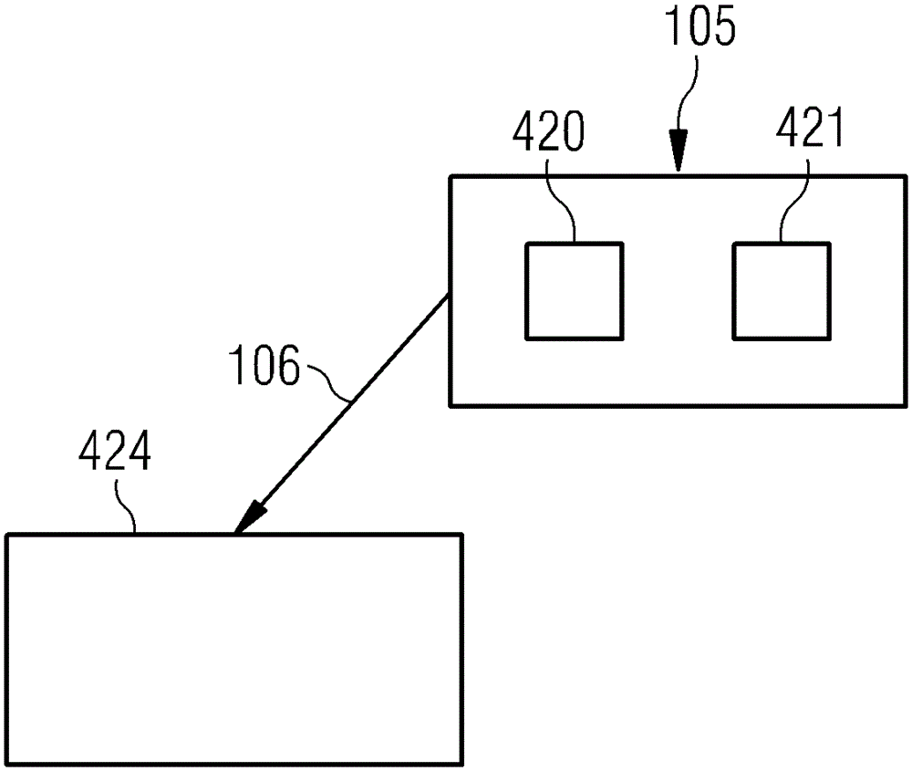
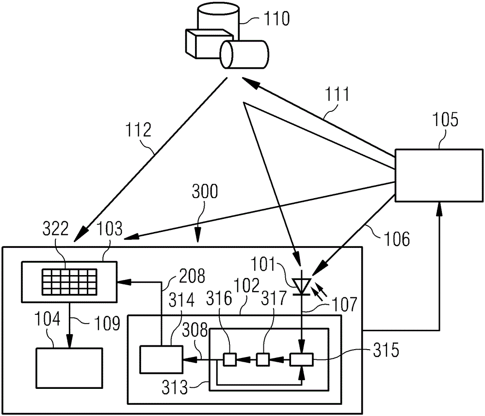
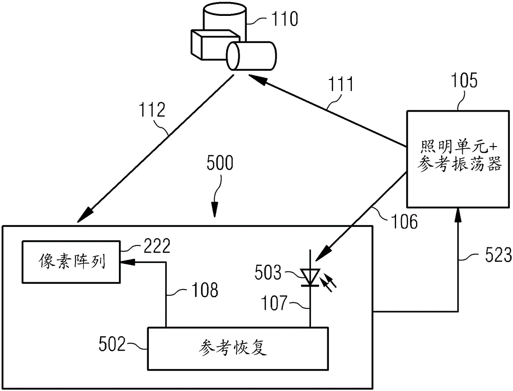
The invention relates to a time of flight apparatuses and an illumination source. The apparatus includes a detector circuit configured to receive a modulated electromagnetic wave signal from an illumination source and to provide a detection signal having a frequency dependent on a modulation frequency of the modulated electromagnetic wave signal. The apparatus further includes a reference circuit configured to generate a reference signal based on the detection signal. The apparatus further includes a sensor circuit configured to generate based on the reference signal a sensor signal based on reflected modulated electromagnetic waves emitted by the illumination source and reflected by an object. The apparatus further includes a processing circuit configured to determine distance information related to the object based on the sensor signal.

Description

technical field [0001] Embodiments relate to determining distance information, and in particular to time-of-flight devices and illumination sources. Background technique [0002] Time-of-flight (TOF) cameras are based on the measurement of the delay between the emission of an optical infrared (IR) signal, which is then reflected by an object, and the reception of the optical signal at a photonic mixing device (PMD) imager. The measured delay is proportional to the object's distance. This principle can be very sensitive to delays caused by components inside the camera. For example, a delay tends to appear between the electrical lighting control signals generated by the chip and the optical signals actually emitted. For example, drivers of lighting units that emit IR signals can cause additional (temperature and voltage dependent) delays, which can distort measurements. Also, the drivers consume a lot of power and can interfere with other sensitive components on the chip. ...

Claims


Application Information

Patent Timeline
IPC IPC(8): G01S17/08G01S17/10G01S7/4865G01S7/4915G01S17/894
CPCG01S17/08H04N23/20G01S17/36G01S7/4915G01S7/497G01S17/894G01S7/4865G01S17/10H04N5/33
Inventor M.迪拉赫尔M.弗拉切尔M.马克J.普赖因扎克
Owner INFINEON TECH AG
Learn More