Cable laying construction method and device

A cable laying and construction method technology, which is applied in the directions of cable installation, cable installation device, cable laying equipment, etc., can solve the problems of complicated installation and inconvenient operation.

Inactive Publication Date: 2016-03-02
STATE GRID SHANDONG LINQU POWER SUPPLY +2
View PDF0 Cites 0 Cited by
  • Summary
  • Abstract
  • Description
  • Claims
  • Application Information

AI Technical Summary

Problems solved by technology

However, other disadvantages such as complex device and inconvenient operation will be produced at this point.

Method used


Image

  • Cable laying construction method and device
  • Cable laying construction method and device
  • Cable laying construction method and device

Examples


Embodiment Construction

[0025] Specific embodiments according to the present invention are described in detail below.

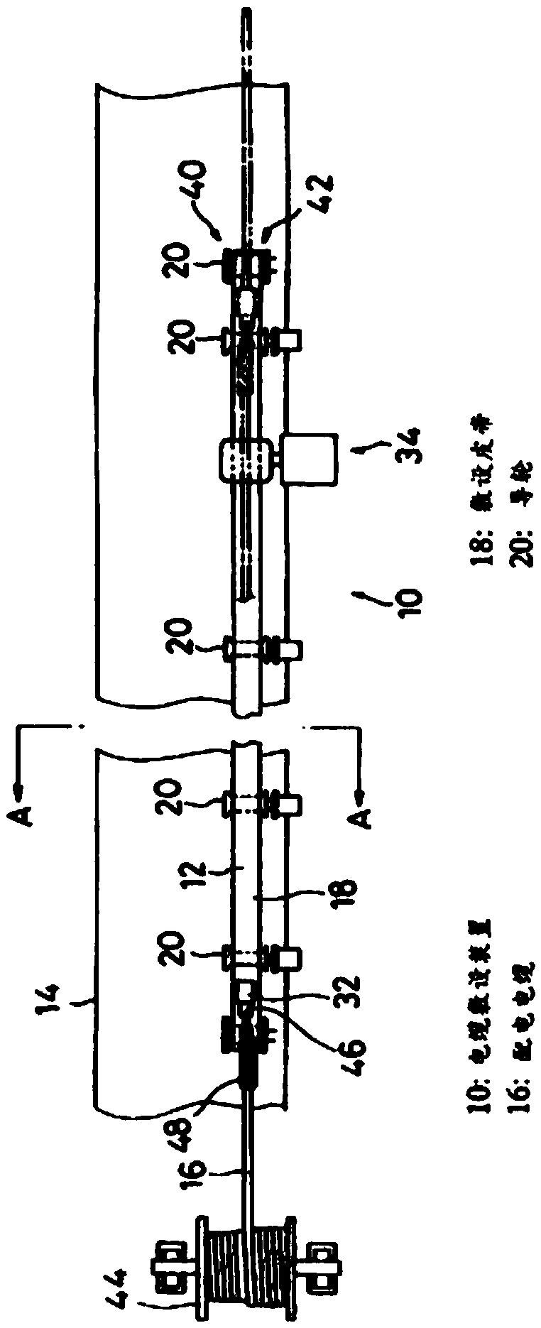
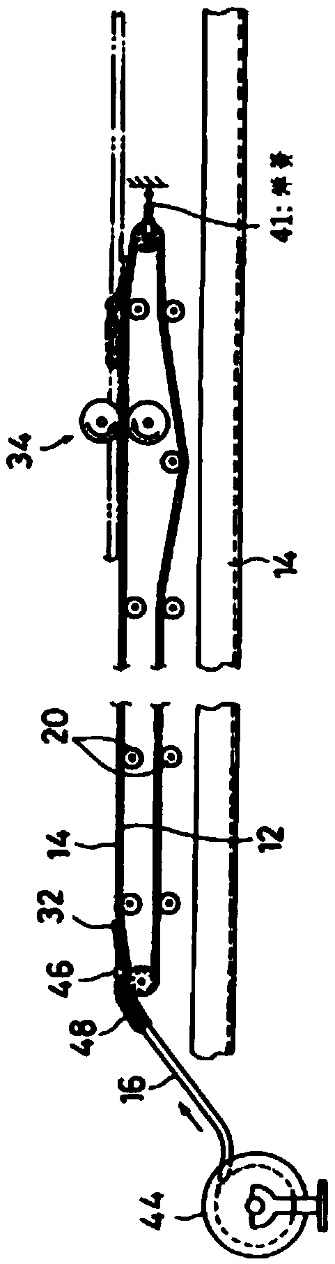
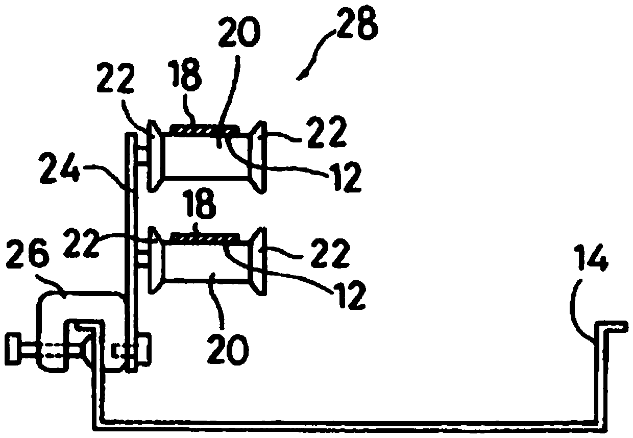
[0026] On the basis of careful consideration, the present invention achieves: when a belt follows the guide pulley, a stable attitude of the belt in operation can be obtained, and thus a power distribution conductor can be pulled reliably.

[0027] The construction method for laying cables according to the present invention includes the steps of: placing an endless laying belt along a cable laying route; connecting cables to a given point of the laying belt; running the laying belt to lay cables along the cable laying route. Here, a construction method may include the following steps: longitudinally placing a plurality of endless laying belts along the cable laying route; Detach from the laying belt; send out the removed cable again; connect the cable to the starting point side of the second laying belt after the cable leaves the first laying belt and arrive at the starting point si...


PUM


Abstract

The objective of the invention lies in conveniently and accurately laying a cable. A cable laying apparatus 10 is constructed, and a laying belt 18 is tensioned by a guide wheel 20. A cable connection apparatus is disposed on the surface of the laying belt 18, and is used for enabling one end of a cable 16 to be connected to the laying belt 18. A driving apparatus 34 and a tensioning apparatus 40 are supplied to the laying belt 18, and are used for operating the laying belt 18 and absorbing the deflection of the laying belt 18. In the above device, the guide surface of the laying belt 18 continuously contacts with the guide wheel 20 even if a tension force is applied to the laying belt 18 from the distribution cable 16, and the posture of the laying belt 18 is not changed, and the laying belt 18 cannot rotate.

Description

technical field [0001] The present invention relates to a construction method for laying cables and a cable laying device, in particular to a construction method for laying cables along a cable laying route in a structure and a cable laying device. Background technique [0002] Generally, a boiler room or the like in a thermal power plant requires a plurality of power distribution cables to be connected between a power room at ground level and control panels or electrical machinery and devices installed on the boiler room. In order to lay the distribution cables in the distribution pipes built in the boiler room, two methods are used: one method is to lift a cable reel with the distribution cables on the boiler room, and then place the distribution cables One end is fed downward from the top open end of the distribution pipe; the other method is to insert one end of the distribution cable into the distribution pipe from the bottom open end of the distribution pipe, and then ...

Claims


Application Information

Patent Timeline
IPC IPC(8): H02G1/08
CPCH02G1/088
Inventor 许朋波尹信吉马新明王倩郑伟马永斌孙好义
Owner STATE GRID SHANDONG LINQU POWER SUPPLY
Why Eureka
Try Eureka