Device and method for detecting continuous light emission of multi-channel optical network unit

A technology of optical network unit and network unit, which is applied in the direction of transmission monitoring/testing/fault measurement system, etc., can solve the problems of inaccurate data, low work efficiency, time-consuming and laborious, etc., and achieve short time consumption, error avoidance and high efficiency Effect

Inactive Publication Date: 2016-03-02
PHICOMM (SHANGHAI) CO LTD
View PDF3 Cites 4 Cited by
  • Summary
  • Abstract
  • Description
  • Claims
  • Application Information

AI Technical Summary

Problems solved by technology

If the ONU optical module in the network is in the long-light state, it will cause network abnormalities
The traditional test method requires the operator to manually power on and off the ONU optical module and read the optical power on the display of the optical power meter, which is time-consuming and laborious, and the operator can only rely on the operator to manually judge whether the product is good or bad, and there are misreadings And operation errors lead to inaccurate data, low work efficiency

Method used


Image

  • Device and method for detecting continuous light emission of multi-channel optical network unit

Examples


Embodiment Construction

[0029] The following will clearly and completely describe the technical solutions in the embodiments of the present invention with reference to the accompanying drawings in the embodiments of the present invention. Obviously, the described embodiments are only some, not all, embodiments of the present invention. Based on the embodiments of the present invention, all other embodiments obtained by persons of ordinary skill in the art without creative efforts fall within the protection scope of the present invention.

[0030] It should be noted that, in the case of no conflict, the embodiments of the present invention and the features in the embodiments can be combined with each other.

[0031] The present invention will be further described below in conjunction with the accompanying drawings and specific embodiments, but not as a limitation of the present invention.

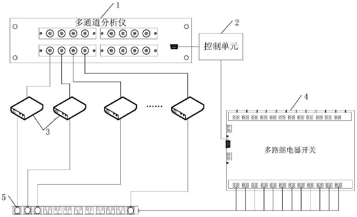
[0032] Such as figure 1 As shown, a device for detecting long luminescence of multiple optical network units is...


PUM


Abstract

The invention discloses a device and method for detecting continuous light emission of a multi-channel optical network unit. The device for detecting continuous light emission of the multi-channel optical network unit comprises a multi-channel relay switch, a multi-channel analyzer and a control unit, wherein the multi-channel relay switch is connected with each optical network unit to be detected and used for controlling turn-on and turn-off of current between each optical network unit to be detected and a power supply; the multi-channel analyzer is connected with each optical network unit to be detected and used for obtaining and outputting the optical power value of each optical network unit to be detected; and the control unit is respectively connected to the multi-channel analyzer and the multi-channel relay switch and used for controlling turn-on or turn-off of the multi-channel relay switch and obtaining the optical power value of each optical network unit to be detected from the multi-channel analyzer, such that whether each optical network unit to be detected is in the continuous light emission state or not can be judged.

Description

technical field [0001] The present invention relates to the field of passive optical network (Passive Optical Network, referred to as PON), in particular to a device and method for detecting long-term emission of multiple optical network units (Optical Network Unit, referred to as ONU). Background technique [0002] With people's demand for high-speed networks, PON products are also accelerating their popularity. However, when testing optical fiber product ONUs, it is necessary to test an important indicator, that is, to detect long-term luminescence. The traditional test method is: use a hand-held optical power meter to detect whether the ONU optical module has optical power when it is powered on. If there is a long light and it is within the test standard, it means that the ONU has a long light. If the ONU optical module in the network is in the long-light state, it will cause network abnormalities. The traditional test method requires the operator to manually power on an...

Claims


Application Information

Patent Timeline
Patent Type & Authority Applications(China)
IPC IPC(8): H04B10/07
CPCH04B10/07
Inventor 汪勇
Owner PHICOMM (SHANGHAI) CO LTD
Why Eureka
Try Eureka