Supercharge Your Innovation With Domain-Expert AI Agents!

Cutting tool

A cutting tool and cutting resistance technology, which is applied in the direction of manufacturing tools, metal processing equipment, milling machine equipment, etc., can solve the problems of cumbersome tool adjustment and achieve the effect of reducing labor

Inactive Publication Date: 2016-03-02
TOYOTA JIDOSHA KK
View PDF7 Cites 0 Cited by
  • Summary
  • Abstract
  • Description
  • Claims
  • Application Information

AI Technical Summary

Problems solved by technology

Therefore, the adjustment of the tool is more cumbersome

Method used


Image

  • Cutting tool
  • Cutting tool
  • Cutting tool

Examples


Embodiment approach 1

[0024] The cutting tool of this embodiment will be described. First, the basic form of the cutting tool according to the present embodiment will be described. The cutting tool of this embodiment can be used, for example, when a hole is formed in a workpiece.

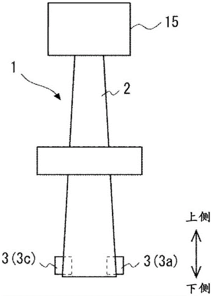
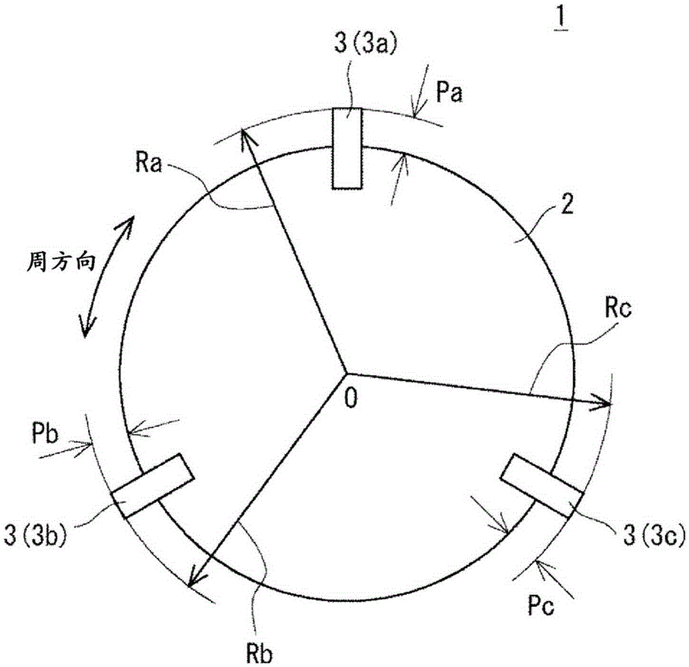
[0025] figure 1 It is a front view schematically showing a state in which the cutting tool 1 according to the present embodiment is connected to the rotary drive mechanism of the cutting device. figure 2 It is a bottom view schematically showing the cutting tool 1 of this embodiment. like figure 1 as well as figure 2 As shown, the cutting tool 1 includes a tool holder 2 and a tool 3 .

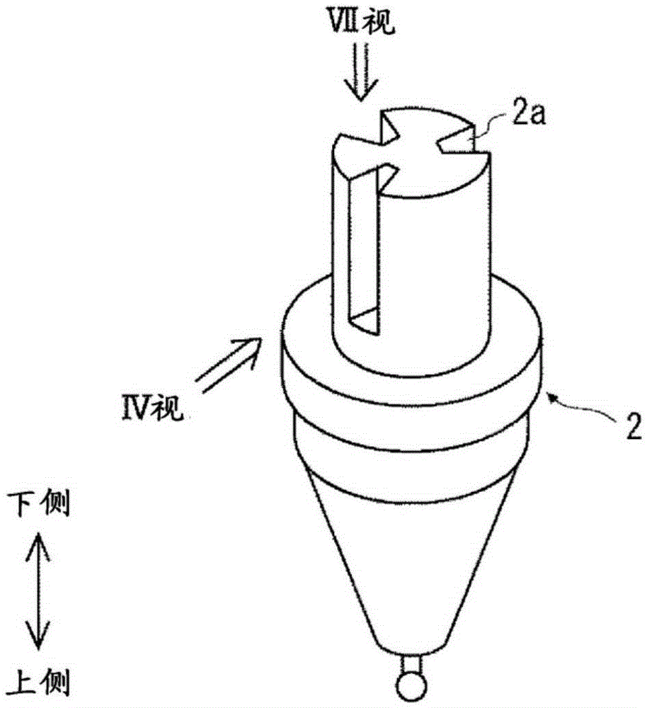
[0026] like figure 1 as well as figure 2 As shown, the tool holder 2 has a substantially conical shape as its basic form, and for example, its upper end is connected to the rotation shaft of the rotary drive mechanism 15 of the cutting device. A cutter 3 is attached to the lower end portion of the cutter holder 2 along the circ...

Embodiment approach 2

[0060] The cutting tool 20 of the present embodiment is composed of the cutting tools 21a, 21b, and 21c made of the same material. Figure 8 It is a bottom view schematically showing the cutting tool 20 of this embodiment. In addition, since the cutting tool 20 of the present embodiment has substantially the same configuration as the cutting tool 1 of the first embodiment, overlapping descriptions are omitted, and the same reference numerals are assigned to the same elements.

[0061] As described above, if the protruding amount Pa of the tool 21a from the tool post 2 in the radial direction of the tool post 2 is greater than the protruding amounts Pb, Pc of the knives 21b, 21c from the tool post 2 in the radial direction of the tool post 2 Larger, the materials of the cutters 21a, 21b, 21c are approximately equal, and the installation angles of the cutters 21a, 21b, 21c are approximately equal, the cutting resistance of the cutter 21a will be greater than that of the cutters ...

Embodiment approach 3

[0066] The cutting tool 30 of the present embodiment is composed of the cutters 31a, 31b, and 31c made of the same material. Figure 9 It is a front view schematically showing the cutting tool 30 of this embodiment. Figure 10 It is a bottom view schematically showing the cutting tool 30 of this embodiment. In addition, since the cutting tool 30 of the present embodiment has substantially the same configuration as the cutting tool 1 of the first embodiment, overlapping descriptions are omitted, and the same reference numerals are assigned to the same elements.

[0067] As described above, if the protruding amount Pa of the tool 31a from the tool post 2 in the radial direction of the tool post 2 is greater than the protruding amounts Pb, Pc of the knives 31b, 31c from the tool post 2 in the radial direction of the tool post 2 Larger, the materials of the cutters 31a, 31b, 31c are approximately equal, and the installation angles of the cutters 31a, 31b, 31c are approximately eq...


PUM


Abstract

A cutting tool which allows the labor associated with adjustment of a cutting edge to be reduced is provided. In the case of a cutting tool (1) pertaining to an embodiment of the present invention, a first cutting edge (3a) and a second cutting edge (3b) are attached to a holder (2). When a direction perpendicular to a vertical direction, in which a side to be connected to a driving mechanism (15) is assumed to constitute the upper side, is defined as a horizontal direction, the protruding amount (Pa) of the first cutting edge (3a) from the holder (2) in a substantially horizontal direction is greater than the protruding amount (Pb) of the second cutting edge (3b) from the holder (2) in the substantially horizontal direction, and the cutting force applied to the workpiece by the first cutting edge (3a) is smaller than the cutting force applied to the workpiece by the second cutting edge (3b) such that a rotary shaft is placed at a position substantially equal to the position of the center of gravity of a horizontal cross-section of the holder (2) when the holder (2) is rotating to cut a workpiece.

Description

technical field [0001] The present invention relates to a cutting tool, and relates to a cutting tool including a plurality of cutting tools. Background technique [0002] A cutting tool is used, for example, to form a hole in a workpiece, and as disclosed in Patent Document 1, a plurality of cutters are attached to a tool holder. At this time, the plurality of knives are attached to the tool holder so that the protruding amounts of the plurality of knives from the tool holder in the substantially horizontal direction are substantially equal. [0003] Patent Document 1: Japanese Patent Laid-Open No. 2001-9627 [0004] In such a cutting tool, a plurality of knives are mounted on the tool holder so that the protruding amounts of the plurality of knives protruding from the tool holder in the substantially horizontal direction are substantially equal. Therefore, it is necessary to readjust all of the plurality of knives after the tool is replaced. The amount of protrusion ment...

Claims


Application Information

Patent Timeline
IPC IPC(8): B23C5/24B23C5/10
CPCB23C5/2472B23C2210/285B23B29/03407B23C5/109B23C5/24B23C5/2226
Inventor 上久保俊孝
Owner TOYOTA JIDOSHA KK
Features
  • R&D
  • Intellectual Property
  • Life Sciences
  • Materials
  • Tech Scout
  • Unparalleled Data Quality
  • Higher Quality Content
  • 60% Fewer Hallucinations
Learn More