Dual-polarized, omnidirectional antenna

An omnidirectional antenna and dual-polarization technology, which is applied to antenna unit combinations, antennas, and antenna couplings with different polarization directions to reduce wind load and minimize visual impact.

Active Publication Date: 2016-03-02
TELEFON AB LM ERICSSON (PUBL)
View PDF18 Cites 2 Cited by
  • Summary
  • Abstract
  • Description
  • Claims
  • Application Information

AI Technical Summary

Problems solved by technology

The disadvantage here is that good omnidirectional emission characteristics can only be achieved for a small frequency range (due to the geometrical arrangement here a phase-dependent attenuation ( ))

Method used


Image

  • Dual-polarized, omnidirectional antenna
  • Dual-polarized, omnidirectional antenna
  • Dual-polarized, omnidirectional antenna

Examples


Embodiment Construction

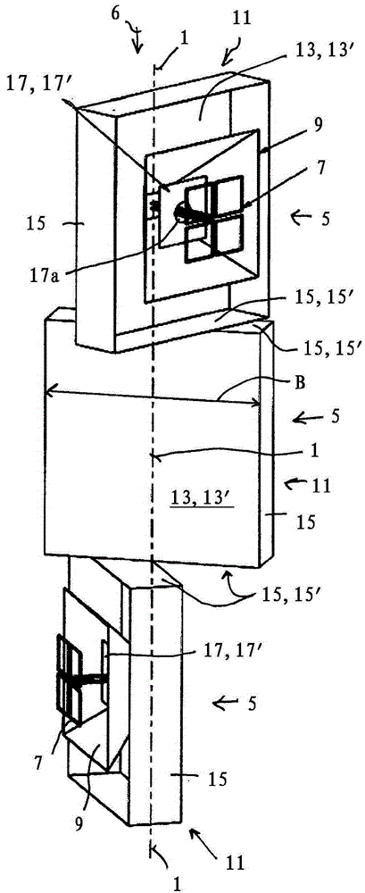
[0049] Refer below Figures 1 to 3 , which shows a first embodiment of the invention.

[0050] figure 1 The vertical central axis 1 , which is also called installation axis or installation line, is shown by dashed lines in .

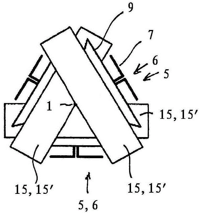
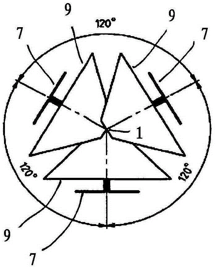
[0051] In the exemplary embodiment shown, three sector antennas 5 are placed one above the other, which are each aligned 120° apart from one another in the azimuth direction in the circumferential direction, ie transmit 120° apart from one another.

[0052] It can be seen here from the figure that the three sector antennas 5 are not arranged at the same height position with respect to their vertical central axis 1 (as is common in the prior art), but along the vertical central axis or installation line The directions of 1 are positioned offset from one another.

[0053] For this purpose, each sector antenna 5 includes, for example, a dual-polarized transmitter 7, for example for a first, higher frequency band (high frequency band) and a further dual p...


PUM


Abstract

An improved dual-polarized, omnidirectional antenna is characterized, inter alia, by the following features: - each sector antenna (5) comprises at least one antenna column (6) comprising an associated reflector (11) which is arranged at least partially in a reflector plane (13'), wherein at least one dual-polarized emitter (7, 9) is arranged in the antenna column (6) in front of the reflector (11), - the sector antennas (5) are additionally arranged offset with respect to one another along the central axis (1) of said sector antennas, - the sector antennas (5) are arranged in such a way that, in an axial view along the central axis (1), the reflectors (11) overlap or intersect one another with the reflector wall (13) of said reflectors, which reflector wall is arranged in a corresponding reflector plane (13').

Description

technical field [0001] The invention relates to a dual-polarized omnidirectional antenna according to the preamble of claim 1 . Background technique [0002] An omnidirectional antenna (Rundstrahler (omnidirectional transmitting antenna)) is known, for example, from WO 2011 / 120090 A1. Such an omnidirectional transmitting antenna comprises, for example, three antenna array arrangements which are each arranged offset from one another at an angle of 120° around the central axis, thus forming a triangular structure in axial plan view. Each antenna array thus covers approximately an azimuth range of 120°. [0003] Corresponding antennas can include various transmitters and transmitter devices according to the prior art, for example dipole antennas, so-called vector dipole antennas, patch transmitters, and the like. So-called dual-polarization vector transmitters are known, for example, from EP057224B1. [0004] Each of the three antenna arrays arranged offset from one another ...

Claims


Application Information

Patent Timeline
IPC IPC(8): H01Q1/24H01Q1/52H01Q21/08H01Q21/20H01Q21/26H01Q25/00
CPCH01Q1/246H01Q1/521H01Q21/08H01Q21/205H01Q21/26H01Q25/005
Inventor M·施托勒M·格特尔
Owner TELEFON AB LM ERICSSON (PUBL)
Why Eureka
Try Eureka