Anti-collision laser head and laser cutting machine and laser head anti-collision method

A technology of laser cutting machine and laser head, which is applied in the field of anti-collision laser head, which can solve the problems of laser head damage, workpiece easy to hit the laser head, etc.

Inactive Publication Date: 2016-03-09
WUHAN GOLDEN LASER
View PDF4 Cites 7 Cited by
  • Summary
  • Abstract
  • Description
  • Claims
  • Application Information

AI Technical Summary

Problems solved by technology

[0003] However, when the knife-blade workbench is processing smaller parts, it is easy to flip or warp on the knife-blade workbench after some parts

Method used


Image

  • Anti-collision laser head and laser cutting machine and laser head anti-collision method

Examples


Embodiment Construction

[0017] The present invention will be further described in detail below in conjunction with the accompanying drawings and specific embodiments.

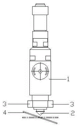
[0018] Please refer to figure 1 , an anti-collision laser head of the present invention, which can prevent the laser head from colliding with an overturned workpiece and damage the laser head. A distance sensor 3 is arranged, and the distance sensor 3 measures the distance from the highest point of the cut workpiece to the lowest point of the laser nozzle. In this embodiment, the laser head main body 1 is provided with two distance sensors 3 , and the two distance sensors 3 are respectively located on opposite sides of the laser head main body 1 . At the same time, four distance sensors 3 can also be arranged on the laser head main body 1 , and the four distance sensors 3 are evenly distributed around the laser head main body 1 . The distance sensor 3 is located at the lower end of the laser head main body 1 .

[0019] The present ...


PUM


Abstract

The invention provides an anti-collision laser head which comprises a laser head body. A laser nozzle is arranged below the laser head body. The laser head body is provided with distance sensors. The distance sensors measure the distance between the highest point of a cut workpiece and the lowest point of the laser nozzle. The position of the highest point of the machined workpiece is measured through the distance sensors, and whether the turned workpiece collides with the laser head or not is judged through the position of the highest point.

Description

technical field [0001] The invention relates to an anti-collision laser head, a laser cutting machine and a method for anti-collision of the laser head. Background technique [0002] During laser processing, especially when processing hard materials such as metal and acrylic, in order to support the workpiece stably and prevent the back of the workpiece from being reflected by the table, the blade-type laser table is widely used in laser cutting. [0003] However, when the knife-blade workbench is processing smaller parts, it is easy to flip or warp on the knife-blade workbench after some parts are cut. When the laser head passes through this area again, the flipped workpiece is easy to hit the laser head , resulting in damage to the laser head. Contents of the invention [0004] The object of the present invention is to provide an anti-collision laser head, which can prevent the laser head from colliding with an overturned workpiece and damage the laser head. [000...

Claims


Application Information

Patent Timeline
IPC IPC(8): B23K26/70B23K26/38
CPCB23K26/38B23K37/006
Inventor 梁伟
Owner WUHAN GOLDEN LASER
Why Eureka
Try Eureka