Laser machining device

a laser machining and laser technology, applied in the direction of soldering devices, manufacturing tools, auxillary welding devices, etc., can solve the problems of attenuated reflected light harming people, harmful to the human body, etc., and achieve the effect of reliably and preventing leakage of reflected laser ligh

Active Publication Date: 2017-06-15
KOIKE SANSO KOGYO CO LTD
View PDF8 Cites 7 Cited by
  • Summary
  • Abstract
  • Description
  • Claims
  • Application Information

AI Technical Summary

Benefits of technology

[0018]In the laser machining device according to the present invention, the entire surface of the machining trolley that travels on the rails is covered with the cover, and the light-blocking members that prevent leakage of the laser light through the gaps between the laser nozzle-side cover body and the garter-side cover body, and the upper surface of the surface plate are attached to lower ends of the laser nozzle-side cover body and the garter-side nozzle body provided on both sides of the machining trolley in the traveling direction. Therefore, the laser light radiated on the material to be machined can be prevented from leaking outside the cover.
[0019]Especially, the light-blocking member has flexibility, and thus even if the plate thickness of the material to be machined placed on the surface plate is changed and the dimension of the gap is changed, the lower end portion of the light-blocking member rubs the upper surface of the surface plate and the upper surface of the material to be machined and is deformed with the traveling of the machining trolley. Therefore, no gap is caused between the surface plate and the upper surface of the material to be machined, and leakage of the reflected laser light from the cover can be prevented.
[0020]Further, the eaves-like cover body formed into an eaves shape in the direction along the rails is attached to the lower end of the laser nozzle-side cover body or the garter-side cover body that configures the cover, and the light-blocking member is attached to the lower end side of the eaves-like cover body. Therefore, leakage of the reflected light can be reliably prevented.
[0021]Further, the light-blocking member is configured from the plurality of sheets that has flexibility and a light-blocking property, and is layered, and the upper end of the layered sheets is attached to the lower end side of the laser nozzle-side cover body, the lower end side of the garter-

Problems solved by technology

However, a part of the reflected laser light is scattered around through a gap formed between the surface of the material to be machine

Method used


Image

  • Laser machining device
  • Laser machining device
  • Laser machining device

Examples


Embodiment Construction

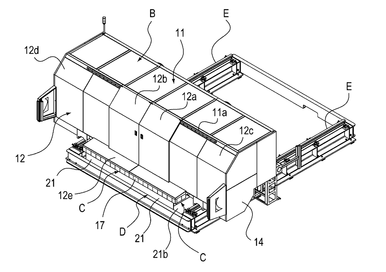
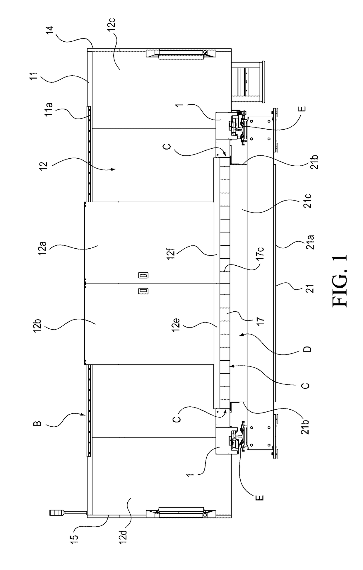
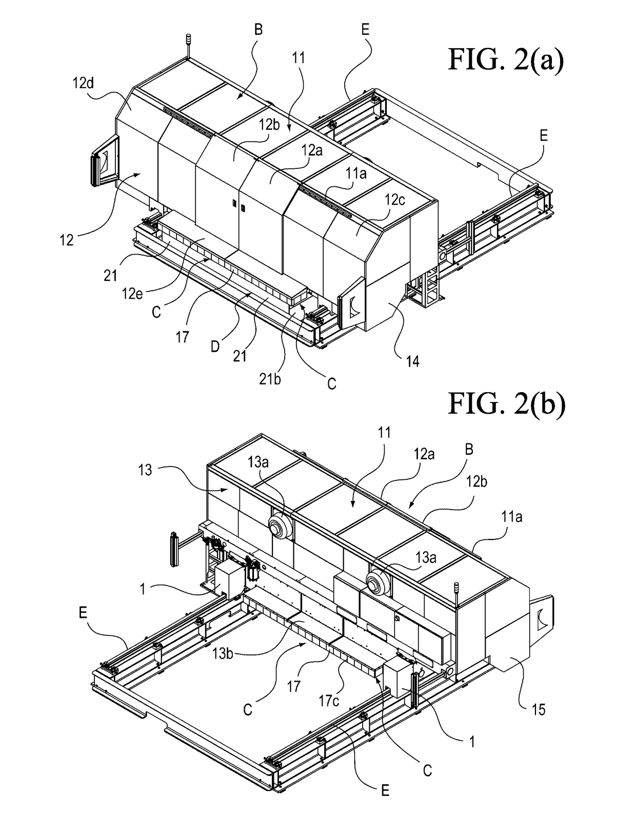
[0030]Hereinafter, a laser machining device according to the present invention will be described. The laser machining device according to the present invention is configured to prevent laser light reflected from a surface of a material to be machined or a molten material in a portion to be machined from leaking outside, in performing cutting machining or welding machining by irradiating the material to be machined with the laser light. Especially, the laser machining device according to the present invention prevents leakage of reflected light through gaps formed between a cover and a surface plate and between the cover and the material to be machined, by covering an entire machining trolley that configures the laser machining device, and providing a light-blocking member having flexibility to lower end portions of a laser nozzle-side cover body and a garter-side cover body arranged in front and back portions in a traveling direction.

[0031]In the present invention, the laser machini...


PUM

PropertyMeasurementUnit
Flexibilityaaaaaaaaaa
Lightaaaaaaaaaa

Abstract

A laser machining device having a surface plate upon which a material to be machined is placed, a rail, a saddle, a garter, a horizontal carriage, and a laser nozzle. On it is attached: a machining trolley that causes the saddle to travel along rail, causes the horizontal carriage to travel horizontally along garter, irradiates laser light from laser nozzle towards a material to be machined, and cuts or welds the material. A cover is provided that covers substantially the entire surface of machining trolley and has an upper surface cover, a laser nozzle-side cover, a garter-side cover, and a side surface body. On a lower end side of the laser nozzle-side cover and the garter-side cover, there is a flexible light-blocking member for preventing laser light from leaking from a gap between the lower end section and the upper surface of the surface plate.

Description

TECHNICAL FIELD[0001]The present invention relates to a laser machining device for cutting or welding a material to be machined by irradiating the material to be machined with laser light, and especially relates to a laser machining device configured to prevent the laser light reflected from a portion to be machined from leaking outside the device.BACKGROUND ART[0002]Cutting or welding by irradiating a material to be machined with laser light through a laser nozzle has been performed. In a case where the material to be machined is a steel plate, a carbon dioxide laser with a wavelength of 10.6 μm is typically used. Further, in recent years, layers having a wavelength of about 1 / 10 the wavelength of the carbon dioxide laser, such as a solid-state laser including a YAG laser, and a fiber laser have received attention as means for machining a steel plate.[0003]Although most of the laser light radiated on a portion to be machined of the material to be machined is absorbed by the materia...

Claims


Application Information

Patent Timeline
IPC IPC(8): B23K26/12B23K26/38B23K26/70B23K26/21
CPCB23K26/128B23K26/706B23K26/38B23K26/21B23K37/0235B23K26/0876B23K26/127B23K26/70B23K26/08B23K26/12
Inventor MARUYAMA, YOICHIMASUDA, SATOSHINAKAGAWA, KEISUKEOMORI, TAKUMI
Owner KOIKE SANSO KOGYO CO LTD
Why Eureka
Try Eureka