Automatic binding machine

A binding machine, fully automatic technology, applied in the direction of binding, etc., can solve the problems of unstable switching, complex linkage structure, unstable binding quality, etc., to achieve the effect of simple and reasonable linkage structure, reasonable linkage structure, and simple structure

Active Publication Date: 2016-03-09
DELI GROUP CO LTD
View PDF7 Cites 16 Cited by
  • Summary
  • Abstract
  • Description
  • Claims
  • Application Information

AI Technical Summary

Problems solved by technology

[0002] The traditional automatic punching and hot riveting binding machine includes an automatic punching device on the upper part of the working panel and a hot riveting device on the lower part, which realizes automatic punching of the bound object, measuring and cutting and sending the riveting tube, and the hot riveting tube is inserted into the hole and then goes up and down End hot riveting binding and other actions, the traditional automatic punc...

Method used


Image

  • Automatic binding machine
  • Automatic binding machine
  • Automatic binding machine

Examples


Embodiment Construction

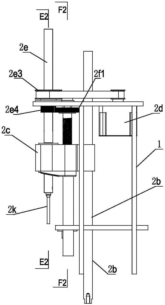
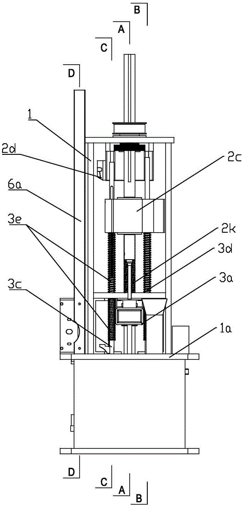
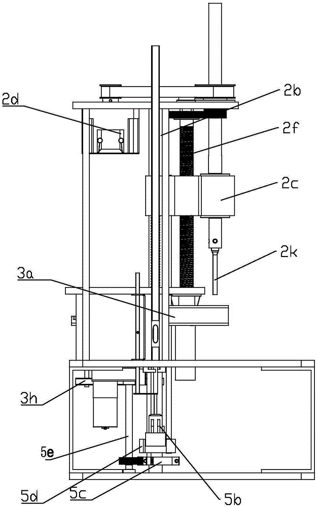
[0072] Such as Figure 1 to Figure 43 As shown, a fully automatic binding machine includes a frame 1, a second motor 1b, a drilling device 2, a lifting seat 2c, a paper pressing device 3, an upper thermal riveting head 3b, a knife shim 4 and a lower thermal riveting head 5b, The vertical guide column 2b and the horizontal work surface 1a are set in the frame 1, the lifting seat 2c can be lifted and positioned on the vertical guide column 2b, and the paper pressing device 3 can be lifted and positioned between the lifting seat 2c and the work table 1a through the spring 3e , the upper hot riveting head 3b is set in the paper pressing device 3 and can move horizontally, the knife shim 4 is set on the working table 1a and can move horizontally, and the lower hot riveting head 5b is positioned on the vertical guide column 2b on the lower side of the horizontal working table 1a It can be lifted and rotated. There is a first rotating link 5e between the upper hot riveting head 3b, t...


PUM


Abstract

The invention relates to an automatic binding machine which comprises a rack, a second motor, a drilling device, a lifting base, a paper pressing device, an upper hot-riveting head, a cutter pad and a lower hot-riveting head. A vertical guide column and a horizontal work table board are arranged in the rack. The lifting base is located on a vertical guide rail in a lifting manner. The paper pressing device is located between the lifting base and the work table board through springs in a lifting manner. The upper hot-riveting head is arranged in the paper pressing device and can horizontally move. The cutter pad is arranged on the work table board and can horizontally move. The lower hot-riveting head is located on the vertical guide column on the lower side of the horizontal work table board and can ascend, descend and rotate. A first rotating connecting rod arranged among the upper hot-riveting head, the cutter pad and the lower hot-riveting head is in rotating linkage. The second motor is connected with the first rotating connecting rod to switch over horizontal dislocation movement between the upper hot-riveting head and the cutter pad and drive the lower hot-riveting head to do rotating dislocation movement. The automatic binding machine can achieve linkage switchover of the upper hot-riveting head, the cutter pad and the lower hot-riveting head through the single motor, and has the advantages that the structure is simple, transmission is reasonable, machining is achieved, and the size and cost are reduced.

Description

technical field [0001] The invention relates to a binding machine, in particular to a fully automatic binding machine. Background technique [0002] The traditional automatic punching and hot riveting binding machine includes an automatic punching device on the upper part of the working panel and a hot riveting device on the lower part, which realizes automatic punching of the binding object, measuring and cutting and sending the riveting tube, and the hot riveting tube is inserted into the hole and then up and down End hot riveting binding and other actions, the traditional automatic punching hot riveting binding machine has disadvantages such as complex interlocking structure and unstable binding quality. At present, the solution to the switching between the upper hot riveting head, the shim, and the lower hot riveting head is usually to add an independent switching mechanism or realize the switching through a rotating structure such as a cam connection, which has the disa...

Claims


Application Information

Patent Timeline
IPC IPC(8): B42B5/02
Inventor 孙兵
Owner DELI GROUP CO LTD
Why Eureka
Try Eureka