Nuclear power plant waste liquid discharge system

A waste liquid discharge, nuclear power plant technology, applied in nuclear engineering, radioactive purification, etc., can solve the problems of uneconomical, reduced tank strength and stability, and low degree of system integration, so as to reduce radiation dose levels and reduce adverse effects Effect

Active Publication Date: 2018-05-29
中广核工程有限公司 +2
View PDF3 Cites 0 Cited by
  • Summary
  • Abstract
  • Description
  • Claims
  • Application Information

AI Technical Summary

Problems solved by technology

However, there are some problems in the design of the above two types of waste liquid discharge systems: ①The inlet valves of the waste liquid storage tanks are all manually controlled valves. The operation of the system has caused great inconvenience, and may cause the operators to suffer excessive radiation doses; ②The waste liquid discharge system is mostly shared by two units, and the degree of system integration is not high. For other units, it is often necessary to repeat the construction of workshops. It will lead to disadvantages such as low degree of commonality of equipment, systems and workshops, and low use efficiency; ③The waste liquid storage tank is equipped with various types of liquid level monitoring instruments, such as liquid level switches, local liquid level indicators and remote liquid level indicators. position transmitter, which often requires digging more holes on the tank body of the waste liquid storage tank, which is not economical and will reduce the strength and stability of the tank itself

Method used


Image

  • Nuclear power plant waste liquid discharge system

Examples


Embodiment Construction

[0029] In order to make the purpose, technical solution and beneficial technical effects of the present invention clearer, the present invention will be further described in detail below in conjunction with the accompanying drawings and specific embodiments. It should be understood that the specific implementations described in this specification are only for explaining the present invention, not for limiting the present invention.

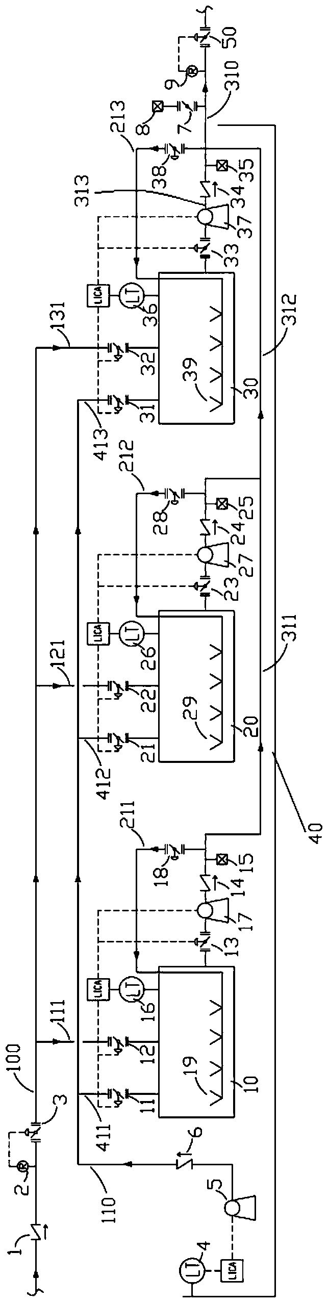
[0030] see figure 1 , the nuclear power plant waste liquid discharge system of the present invention comprises three waste liquid storage tanks 10, 20, 30, waste liquid input pipeline 100, waste liquid discharge pipeline 310, waste liquid mixing device, pit 40, pit liquid discharge pipeline 110 and System control device (not shown). The waste liquid input pipeline 100 is connected to the upstream of the waste liquid storage tank 10, 20, 30, and is used to input the waste liquid to be discharged into the waste liquid storage tank 10, 20, 30; the w...


PUM


Abstract

The invention discloses a discharge system of waste liquid in nuclear power plant. The waste liquid input pipeline of the discharge system comprises a main input pipeline and multiple branch input pipelines, wherein the main input pipeline is connected to the waste liquid discharge pipeline of the upstream system and the branch input pipelines are respectively connected to the inlets of different waste liquid storage tanks; an inlet isolation valve is arranged on each of the branch input pipelines; all the inlet isolation valves are connected to the system control device and are opened and closed by the system control device according to the preset interlock control information, so as to ensure that the waste liquid from the upstream system can be automatically input into available waste liquid storage tanks and automatic alternations between the waste liquid storage tanks are realized. Compared with prior art, remote control to the inlet isolation valves by the system control device is realized in the discharge system of waste liquid in nuclear power plant disclosed by the invention; and the automatic alternations between the waste liquid storage tanks are realized by setting of the logic control program; thus, the discharge system of waste liquid in nuclear power plant is capable of automatically and continuously receiving the waste liquid discharged from the upstream system, so that the adverse effects to the system caused by error operations of the operators are reduced to the minimum; moreover, the radiation dose level suffered by the operators are thereby reduced.

Description

technical field [0001] The invention belongs to the field of nuclear power plant radioactive waste liquid discharge, and more specifically, the invention relates to a nuclear power plant waste liquid discharge system. Background technique [0002] According to the principles of "optimization of radiation protection" and "minimization of waste", when the potentially radioactive or low-level radioactive waste liquid generated during the operation of the nuclear power plant is discharged to the external environmental water body, it needs to meet the trough discharge requirements. [0003] According to the source and composition of the waste liquid, the low-level waste liquid (potentially radioactive waste liquid) generated during the operation of the nuclear power plant is mainly divided into two categories: conventional island waste liquid and nuclear island waste liquid. The waste liquid discharged from the conventional island mainly comes from the low-level waste liquid coll...

Claims


Application Information

Patent Timeline
Patent Type & Authority Patents(China)
IPC IPC(8): G21F9/22
CPCG21F9/22
Inventor 于世昆李俊苹姚兵白婴潘跃龙
Owner 中广核工程有限公司
Why Eureka
Try Eureka