
A new type of high-precision locking device in place

A locking device, high-precision technology, applied in antennas, folded antennas, electrical components and other directions, can solve the problem of not having adaptive locking, the specific structure of the locking mechanism has not been found in relevant literature reports, and does not meet the Ka-band umbrella antenna type. Surface requirements and other issues to achieve the effect of improving the repeatability of unfolding, achieving self-adaptation, and stable locking state

Active Publication Date: 2018-08-07
XIAN INSTITUE OF SPACE RADIO TECH
View PDF5 Cites 1 Cited by
  • Summary
  • Abstract
  • Description
  • Claims
  • Application Information

AI Technical Summary

Problems solved by technology

[0004] According to the information, Russia's "Ray No. 5" umbrella antenna has the function of locking in place, and its mechanism adopts the principle of self-locking of the connecting rod, which does not have the function of self-adaptive locking, and there is still a small gap after locking. It meets the profile requirements of the Ka-band umbrella antenna; the umbrella antenna developed by the United States and applied to the relay satellite TDRS also has the function of locking in place, but there is no relevant literature report on the specific structure of the locking mechanism

Method used


Image

  • A new type of high-precision locking device in place
  • A new type of high-precision locking device in place
  • A new type of high-precision locking device in place

Examples


Embodiment Construction

[0027] The implementation process of the present invention will be described in detail below in conjunction with the accompanying drawings and specific examples.

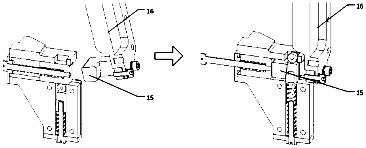
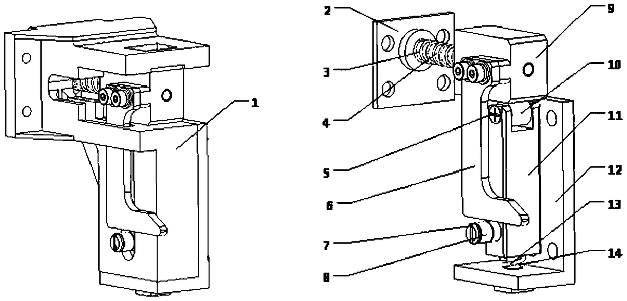
[0028] Such as figure 2 Shown is a schematic diagram of the structure of the locking device in the untriggered state. It can be seen from the figure that it includes the chute 1, the blocking plate 2, the guide rod 3, the second spring 4, the customized screw 5, the limit plate 6, the pin 7, and the second roller 8 , pallet 9, first roller 10, stop pin 11, cover plate 12, first spring 13 and spring guide column 14; chute 1 is the base of all parts, and provides support for pallet 9 and stop pin 11 Sliding rails, both rails are vertical. The horizontal direction is the sliding track of the supporting plate 9, the second spring 4 is set on the guide rod 3, one end is pressed against the supporting plate 9, and the other end is pressed against the blocking plate 2, the blocking plate 2 is installed on the chute 1, an...


PUM


Abstract

A novel high-precision in-position locking device relates to the technical field of a space-expandable mechanism, including a chute, a limiting plate, a second roller, a supporting plate, a stop pin, a cover plate, and a locking connection block. The chute is the base of all parts, and provides the sliding track of the pallet and the stop pin, and the two tracks are orthogonal; the horizontal direction is the sliding track of the pallet, and the vertical direction is the sliding track of the stop pin. The limit plate is installed on the supporting plate, and blocks the second roller when the locking device is not triggered, and the limit plate slides on the second roller after triggering; the present invention adopts the linkage scheme of two sets of spring drive components, which is applied in the space On the high-precision expandable mechanism, the state is solidified after the mechanism is deployed in place, the repeated deployment accuracy is improved to no more than 0.01°, and the self-adaptive locking is realized, the matching gap between the two is eliminated, and the repeated deployment accuracy is improved. .

Description

technical field [0001] The invention relates to the technical field of space expandable mechanisms, in particular to a novel high-precision locking device in place. Background technique [0002] The present invention originates from the development of the deployment mechanism of the high-precision radial rib umbrella-shaped deployable antenna. In order to meet the envelope requirements during satellite launch, the large-diameter antenna should have the characteristics of high storage ratio, and the antenna should be locked and stored in the satellite during satellite launch. On the platform, after being in orbit, it will be deployed into a working state, such as figure 1 As shown, the rib deployment mechanism is used to drive the main reflector of the antenna to expand from the retracted state to the working state. [0003] The high-precision radial rib umbrella-shaped deployable antenna works in the Ka frequency band, and the on-orbit profile accuracy of the antenna is req...

Claims


Application Information

Patent Timeline
Patent Type & Authority Patents(China)
IPC IPC(8): H01Q1/08H01Q15/16
Inventor 李菡王波师甜程建刘翔勇
Owner XIAN INSTITUE OF SPACE RADIO TECH
Learn More