
IC tag provided with three-dimensional antenna and pallet provided with the IC tag

a three-dimensional antenna and ic tag technology, applied in the field of ic tags, can solve problems such as easy interference, and achieve the effects of increasing the output power intensity of the ic tag, and reducing the size of the ic chip and the ic tag

Inactive Publication Date: 2005-11-03
FUJIFILM BUSINESS INNOVATION CORP
View PDF5 Cites 91 Cited by
  • Summary
  • Abstract
  • Description
  • Claims
  • Application Information

AI Technical Summary

Benefits of technology

[0010] In the planar antenna, the radio wave length and the communication method are not particularly restricted, and various types such as the electrostatic coupling type, the electromagnetic coupling type, the electromagnetic induction type, and the microwave type are feasible. In addition, the kinds of antennas corresponding to the above types are not particularly restricted, provided that they can be configured to be surface-shaped (planar or curved surface-shaped and may be constructed over a multiple layers). For example, a dipole antenna, a coil antenna, a patch antenna, etc. can be used. It is also possible to employ, as the shape of the antenna, various shapes such as circular and rectangular shapes, and it is also possible, for example, to employ an antenna having an antenna pattern that is a spiral pattern and the square wave pattern which can be efficiently arranged in a surface-shaped structure for avoiding multi-level crossing.
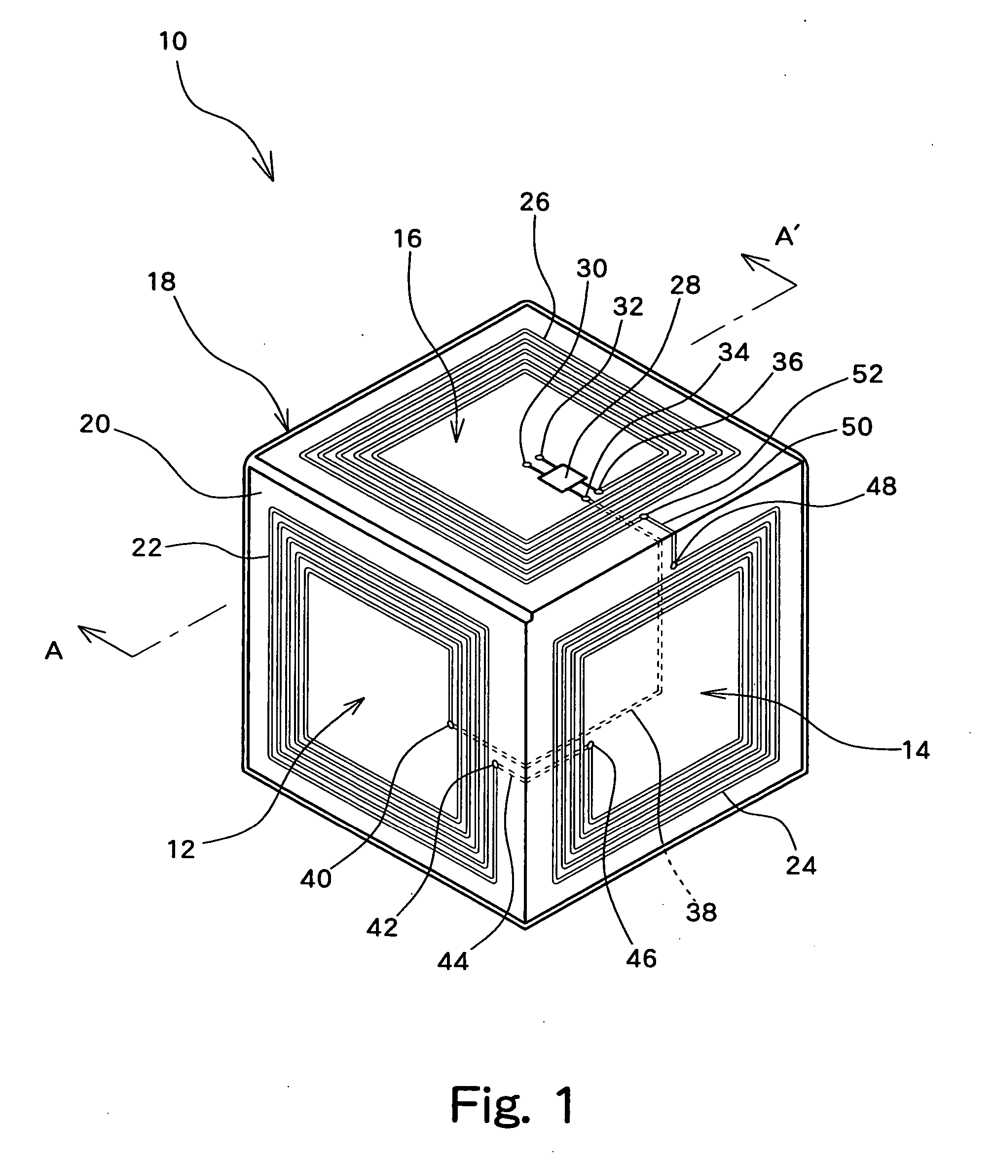
[0013] According to such a configuration, plural planar antennas, each capable of functioning by itself, are arranged in three dimensions, thereby reducing a weak spot in the directivity of each planar antenna. That is, compared with the case where a planar antenna is used as a single unit, excellent transmission and reception can be performed over a wide angular range. For this reason, communication faults can be prevented in the case where the installation angle of the antenna of the IC tag is difficult to specify due to the storage conditions and the conveying state of a product and a carrier container to which the IC tag is attached, and where the adjustment of the angular relationship with respect to the reader / writer is difficult.
[0014] The IC tag can be a type with a built-in battery as a power source (active type). As a result, the output power intensity of the IC tag can be increased, and also the antenna output power at the side of the reader / writer can be suppressed. The IC tag may be a type without a built-in battery and driven by the energy of received radio waves as a power source (passive type). In this case, the size of the IC tag can be reduced. The IC tag may also be constructed such that some components necessary for the operation of the IC tag, such as an oscillator, etc. for use in generation of a carrier wave and in demodulation at the time of reception, are externally separately provided, and connected by means of wiring for operating the IC tag. As a result, size reduction of the IC chip and IC tag can be achieved.

Problems solved by technology

However, such an antenna is not typically employed, because it causes the configuration to be redundant and it is easy for interference to occur, especially at the time of transmission.

Method used


Image

  • IC tag provided with three-dimensional antenna and pallet provided with the IC tag
  • IC tag provided with three-dimensional antenna and pallet provided with the IC tag
  • IC tag provided with three-dimensional antenna and pallet provided with the IC tag

Examples


Embodiment Construction

[0027] A plurality of embodiments according to the invention is described with reference to the drawings below.

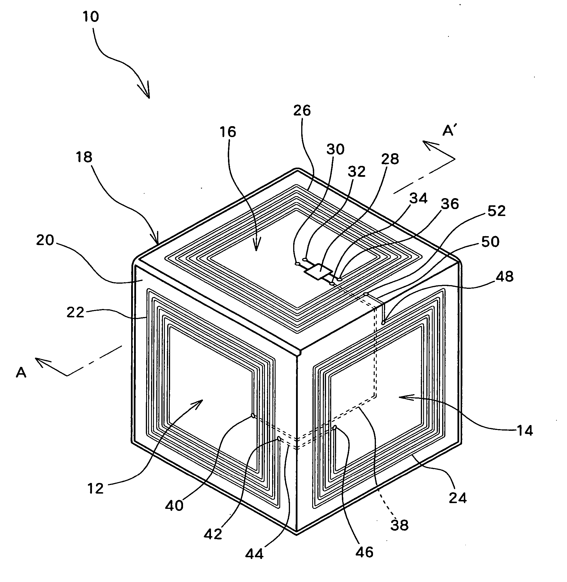
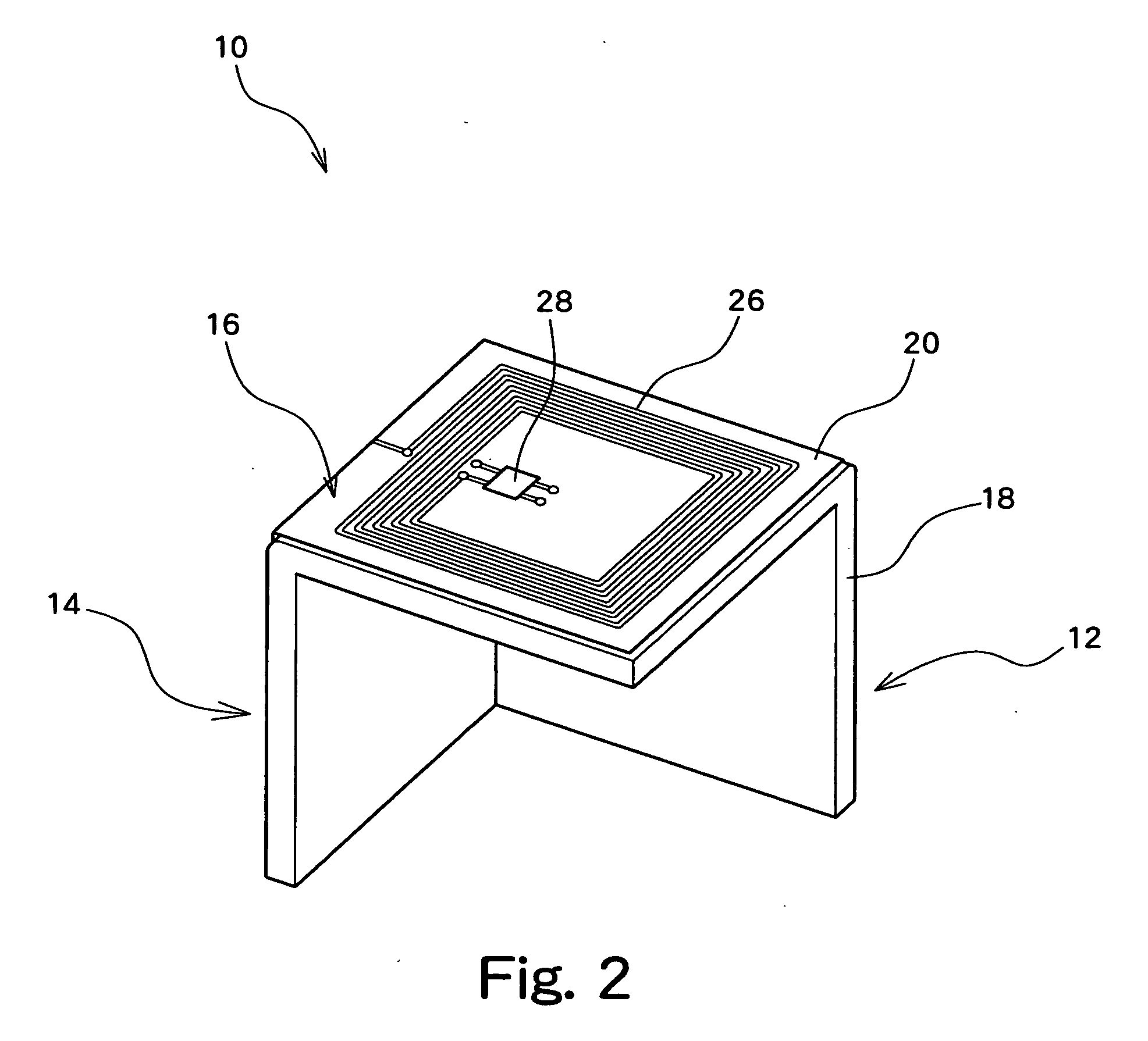
[0028]FIG. 1 is a perspective view of an exemplary embodiment of an IC tag according to the invention, viewed from a front side upper part, and FIG. 2 is a perspective view of the same IC tag viewed from a rear side upper part. The IC tag 10 is formed in such a manner that three square plates are connected to each other at their circumferential parts. That is, the IC tag is shown as a form of three surfaces taken out from a cube having three surfaces 12, 14, 16 which are orthogonal to each other. This form has a base 18 as a base material. The base 18 is processed into this form by molding of a synthetic resin. The IC tag is typically sized such that the length of one side of each surface 12, 14, 16 is about several cm (for example, 5 cm), but may be adapted to be longer or shorter depending on the size required for the antenna described below.

[0029] A base film 20 as a f...


PUM


Abstract

The IC tag comprises a three-dimensional antenna and an integrated circuit. The three-dimensional antenna is configured in such a manner that a plurality of planar antennas, each capable of performing emission and reception of radio waves by itself, are arranged at angles so as to be not parallel to each other. The integrated circuit is also connected to the three-dimensional antenna and performs transmission or reception of a signal via the three-dimensional antenna.

Description

BACKGROUND OF THE INVENTION [0001] 1. Field of the Invention [0002] The present invention generally relates to an IC tag which is provided with an antenna and integrated circuit and which is capable of reading or writing data through radio waves, and more particularly to a technique regarding the construction of the antenna. The invention is also related to a technique of attaching the IC tag to a carrying container of an article. [0003] 2. Description of the Related Art [0004] IC tags (which may be referred to as RFID (Radio Frequency IDentification) tags etc.) attached to a product and a carrier container, etc. have spread rapidly in recent years. The IC tag is a small and lightweight device having an integrated circuit (IC) and antenna, and is utilized for the distribution and function management, etc. of an article provided with the IC tag, by writing and reading information into and out of the integrated circuit. For example, in the field of image processing devices, such as a ...

Claims


Application Information

Patent Timeline
IPC IPC(8): G06K19/00B65D19/38G06K19/07G06K19/077G08B13/14H01Q7/00H01Q21/24
CPCG06K19/07749G06K19/0775G06K19/07767G06K19/07779G06K19/07783H01Q21/24G08B13/2431G08B13/2434G08B13/2445H01Q7/00G06K19/07792B65D2203/10
Inventor WATANABE, TOSHIO
Owner FUJIFILM BUSINESS INNOVATION CORP
Learn More