
Multi-mode slot antenna and mobile terminal

A technology for slot antennas and mobile terminals, applied to antennas, antenna equipment with additional functions, and devices that enable antennas to work in different bands at the same time, can solve problems such as high cost, complex structure, and large volume of mobile terminals. Complexity, reduced production cost, and the effect of eliminating the NFC antenna structure

Active Publication Date: 2016-03-09
GUANGDONG OPPO MOBILE TELECOMM CORP LTD
View PDF7 Cites 5 Cited by
  • Summary
  • Abstract
  • Description
  • Claims
  • Application Information

AI Technical Summary

Problems solved by technology

[0004] The present invention provides a multi-mode slot antenna and a mobile terminal to solve the problems of large size, complex structure and high cost of existing mobile terminals with NFC function

Method used


Image

  • Multi-mode slot antenna and mobile terminal
  • Multi-mode slot antenna and mobile terminal
  • Multi-mode slot antenna and mobile terminal

Examples


Embodiment Construction

[0023] The present invention will be further described in detail below in conjunction with the accompanying drawings and embodiments. It should be understood that the specific embodiments described here are only used to explain the present invention, but not to limit the present invention. In addition, it should be noted that, for the convenience of description, only some structures related to the present invention are shown in the drawings but not all structures.

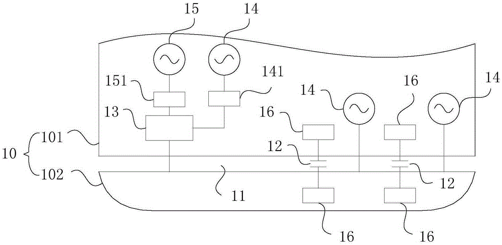
[0024] figure 1 It is a structural schematic diagram of a multi-mode slot antenna provided in a specific embodiment of the present invention. Such as figure 1 As shown, the multi-mode slot antenna includes:

[0025] Metal plate 10 , at least two blocking capacitors 12 , combined feed matching circuit 13 , at least two far-field feed structures 14 and one near-field feed structure 15 .

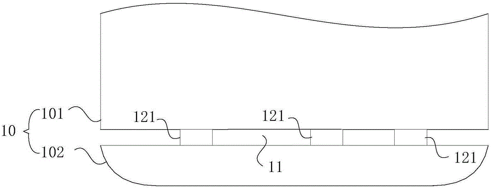
[0026] Wherein, the metal plate 10 is provided with a slit 11, and the slit 11 divides the metal plate 10 into a ground end 10...


PUM

PropertyMeasurementUnit
Capacitanceaaaaaaaaaa

Abstract

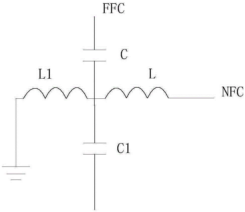
The invention discloses a multi-mode slot antenna and a mobile terminal. The multi-mode slot antenna comprises: a metal plate, wherein a slot is formed in the metal plate and used for dividing the metal plate into a ground end and an antenna end; at least two partition capacitors, wherein the two ends of the partition capacitors are connected with the two sides of the slot respectively, the slot is divided into a plurality of feed regions, and one of the partition capacitors is a shared partition capacitor; a combining feed matching circuit, wherein the combining feed matching circuit multiplexes the shared partition capacitor, and the combining feed matching circuit also comprises a capacitor C, an inductor L and an inductor L1; at least two far field feed structures, wherein one far field feed structure is a first far field feed structure, and the first far field feed structure is connected with the other end of the capacitor C; and a near field feed structure, wherein the near field feed structure is connected with the other end of the inductor L. According to the multi-mode slot antenna, the slot is shared through a near field communication structure and a far field communication structure; and the multi-mode slot antenna is simple in structure and low in cost.

Description

technical field [0001] The embodiments of the present invention relate to the technical field of antennas, and in particular to a multi-mode slot antenna and a mobile terminal. Background technique [0002] With the continuous development of mobile terminals and wireless communication technology, NFC (Near Field Communication, near-field communication) technology, as a short-range high-frequency wireless communication technology, can realize electronic payment, Functions such as intelligent identification and data transmission, NFC technology has also been widely used due to its above-mentioned unique advantages. [0003] The NFC antenna installed on the mobile terminal generally occupies a large volume, and in order to avoid mutual interference with the far-field communication antenna in the mobile terminal, it is necessary to add an expensive ferrite with a comparable area to the NFC antenna. With the increase of wireless communication functions of mobile terminals, more ...

Claims


Application Information

Patent Timeline
IPC IPC(8): H01Q1/36H01Q1/44H01Q5/328H01Q5/50
Inventor 向胜昭
Owner GUANGDONG OPPO MOBILE TELECOMM CORP LTD
Learn More