
An ultra-wideband tem horn antenna and its modeling method

A horn antenna and ultra-broadband technology, applied in antennas, waveguide horns, electrical components, etc., to achieve the effect of optimizing the pattern, optimizing the standing wave ratio, and frequency bandwidth

Active Publication Date: 2018-05-22
江苏肯立科技股份有限公司
View PDF5 Cites 0 Cited by
  • Summary
  • Abstract
  • Description
  • Claims
  • Application Information

AI Technical Summary

Problems solved by technology

[0004] In order to solve the high-frequency pattern sidelobe of the ultra-wideband horn in the prior art, the main lobe bifurcates prematurely in the high-frequency band, the present invention proposes an ultra-wideband TEM horn antenna and a modeling method

Method used

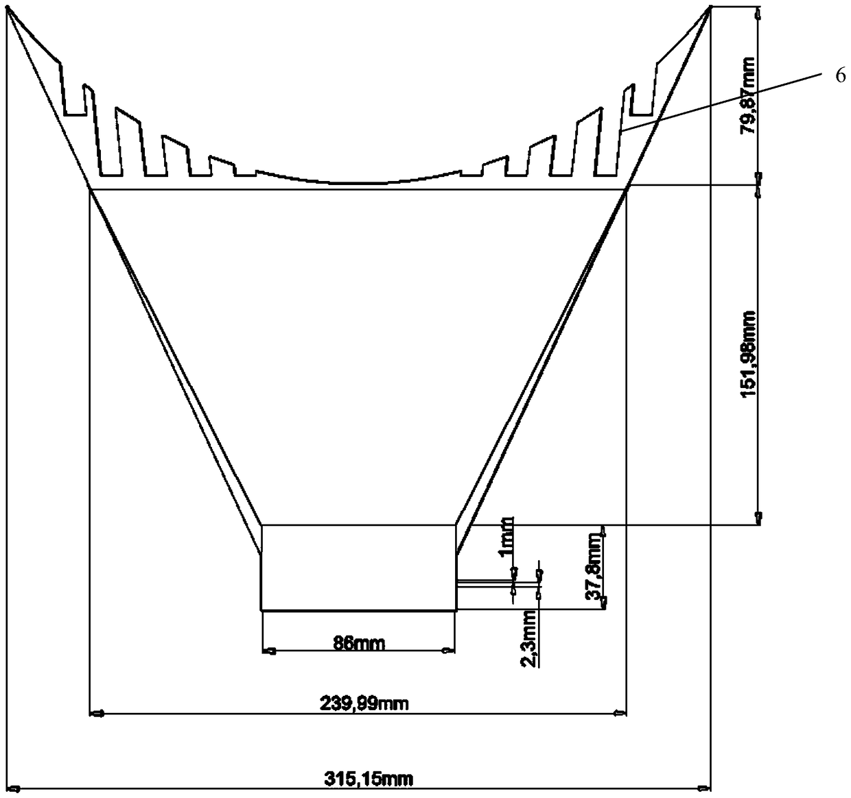
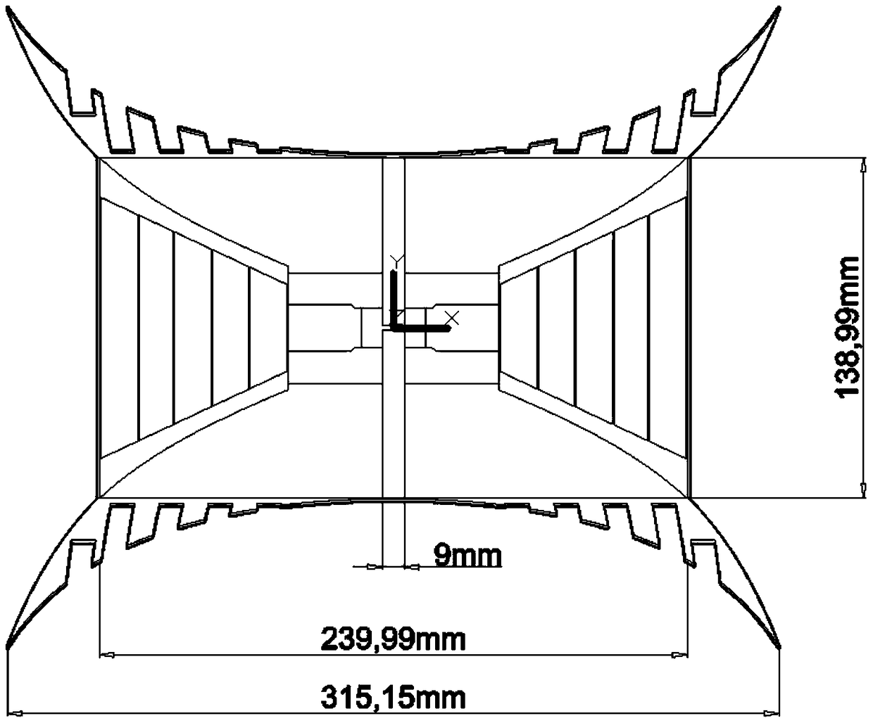
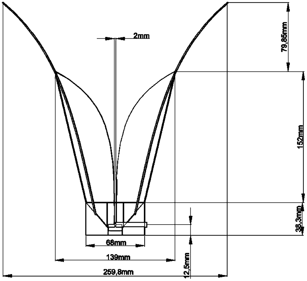

Image

  • An ultra-wideband tem horn antenna and its modeling method
  • An ultra-wideband tem horn antenna and its modeling method
  • An ultra-wideband tem horn antenna and its modeling method

Examples


Embodiment Construction

[0041] The present invention will now be further described in conjunction with the embodiments and accompanying drawings:

[0042] like Figure 1-4 As shown, the ultra-wideband TEM horn antenna includes a shorting plate 1, a feeding part 2, a ridge waveguide section 3 and a horn section 4; The shaft connector, the inner core of which is connected to the lower ridge, and the outer side of the inner core is provided with a thickened part for adjusting the standing wave; the shorting plate 1 is located at the rear end of the ridge waveguide section 3; on the two narrow walls of the ridge waveguide section 3 There is a wedge body with a high outer side and a low inner side; in order to reduce the weight of the horn antenna, the two narrow walls of the horn section 4 are made of dielectric plates. A metal wire, and a ridge 5 with an exponential curve (y=1.1*exp(0.0253*z)-0.03365*z) is respectively provided on the two wide walls of the horn section 4, and the ridge 5 is fed from th...


PUM


Abstract

The present invention relates to an ultra wideband TEM speaker antenna and a modeling method. By adjusting a spinal curve, changing a speaker wide surface into a exponential curved surface structure, and designing a unique structure at the opening of a speaker to extend the wide surface, a high frequency direction pattern is optimized, and thus the high frequency performance of an ultra wideband speaker is enhanced.

Description

technical field [0001] The invention belongs to electromagnetic field, microwave and antenna technology, in particular to a horn antenna and a modeling method. The horn antenna is used for signal transmission and reception. Background technique [0002] UWB horn antennas have been widely used in measurement, radar and communication systems. In the existing ultra-wideband speakers, the high-frequency pattern is not very ideal: the high-frequency pattern has higher side lobes, and the main lobe bifurcates prematurely in the high frequency band. The surface is changed to an exponential surface structure, and a unique structure is designed at the bell mouth to extend the wide surface, optimizing the high-frequency pattern, thereby enhancing the high-frequency performance of the ultra-wideband speaker. SUMMARY OF THE INVENTION [0003] technical problem to be solved [0004] In order to solve the problem of premature bifurcation in the high-frequency frequency band of the hig...

Claims


Application Information

Patent Timeline
Patent Type & Authority Patents(China)
IPC IPC(8): H01Q13/02
CPCH01Q13/0275H01Q13/0283
Inventor 杨林魏庚明栗曦周鹏伊向杰
Owner 江苏肯立科技股份有限公司
Learn More