Air flow reversing element with bypass tube and method of controlling patient exhalation

A technology of reversing elements and bypass pipes, which is applied in the direction of respirator, medicine equipment, and other medical equipment, etc., can solve the problems of blockage of airflow reversing elements and inability to ensure that patients can provide a predetermined amount and concentration.

Active Publication Date: 2018-07-06
VENTINOVA TECH
View PDF8 Cites 0 Cited by
  • Summary
  • Abstract
  • Description
  • Claims
  • Application Information

AI Technical Summary

Problems solved by technology

As a result, there is a risk that the flow reversing element will become clogged with liquid blocked by condensation of the suction flow
In addition, it cannot guarantee that predetermined amounts and concentrations of drugs and / or anesthetics will be delivered to patients

Method used


Image

  • Air flow reversing element with bypass tube and method of controlling patient exhalation
  • Air flow reversing element with bypass tube and method of controlling patient exhalation
  • Air flow reversing element with bypass tube and method of controlling patient exhalation

Examples


Embodiment Construction

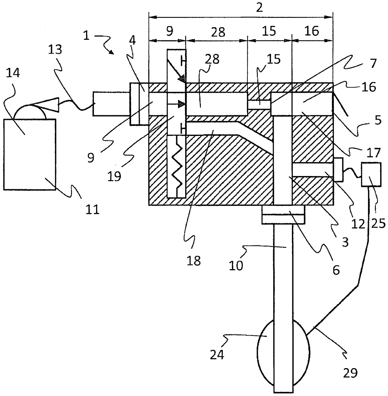
[0086] figure 1 A longitudinal section through the air flow reversing element 1 with the main part 2 connecting the pressure connection 4 to the outlet opening 5 is shown. The pressure connection 4 can be connected via a connecting pipe 13 to a gas source 14 in a compressed gas source 11 , which is under excess pressure. Compressed oxygen tanks are generally manufactured for use in emergency patient care. Additionally, complex gas mixtures may be provided as gas source 14 . The part extending from the main part 2 is a branch part 3 which leads to a pipe connection 6 . In the main part 2 , an inflow area 9 , a flow area 28 , a nozzle area 15 with nozzles 7 and a mixing area 16 with mixing channels 17 are realized. Inside the nozzle zone 15 there are nozzles 7 through which gas can flow from the pressure connection 4 to the outlet opening 5 . This nozzle 7 is located near the branch 3 so that the gas flowing through the nozzle 7 to the outlet hole 5 creates an underpressure ...


PUM


Abstract

A gas flow reversing element (1) using a gas source (14) under overpressure, in particular suction gas, for selectively generating a gas flow (8) from or to a pipe connection (6), in particular Can be connected to the patient's airway, the air flow reversing element (1) is designed as a main part (2) and an additional branch part (3), the main part (2) at least includes an inflow area (9), a nozzle area ( 15) and a mixing zone (16), the inflow zone (9) connects the pressure connection (4) for connection to the gas source (14) to at least one closable outlet hole ( 5), and the branch piece (3) connects the nozzle area (15) of the main part (2) to the pipe joint (6), wherein the nozzle (7), especially the injection nozzle, is configured and arranged in the nozzle area (15) , so that when the outlet hole (5) is opened, the air flow (8) flowing to the outlet hole (5) along the first flow path (20) through the main part (2) can be generated in the branch part (3) The gas flow (8) flowing to the outlet hole (5) along the second flow path (21), wherein the first flow path starts from the pressure joint (4), sequentially passes through the inflow zone (9), the flow zone (28) , the nozzle area (15), and enter the mixing area (16) through the nozzle (7), and the second flow path starts from the pipe joint (6), and passes through the branch piece (3), through the nozzle area (15) , and through the mixing zone (16), wherein the air flow reversing element (1) also includes a bypass pipe (18), which connects the pressure joint (4) and the pipe joint (6), so that the air flow (8) can Flow along a third flow path (22) via the inflow zone (9), the bypass tube (18) and the branch piece (3), wherein at least the bypass tube (18) and the flow zone (28) are closed by at least one The element (19) is closable so that the gas flow (8) can bypass the nozzles (7) in the nozzle zone (15) along the third flow path (22) via the bypass line (18). The invention also relates to a method of controlling a patient's exhalation.

Description

technical field [0001] The invention relates to a gas flow reversing element and a method for operating it in order to generate a gas flow selectively from or to a fitting for gas exchange in a closed or partially closed (local) area of ​​a patient's airway. The invention further relates to a method for ventilation of a patient via a gas flow reversing element. The invention also relates to a method of controlling a patient's exhalation. One use involves connecting such a flow diverting element to one lumen (such as a catheter or needle) that can be inserted into the patient's airway, or to multiple lumens connected sequentially and / or in parallel (bronchoscope, bronchial blocker tube, laryngeal mirror, etc.). Background technique [0002] To ventilate the patient, a mask or tube is usually used, by means of which a gas or a gas mixture, in particular oxygen and air, is delivered at low pressure from the outside to the unsealed airway. Alternatively, however, this type of...

Claims


Application Information

Patent Timeline
Patent Type & Authority Patents(China)
IPC IPC(8): A61M16/00A61M16/12
CPCA61M16/0096A61M16/0434A61M16/1075A61M16/12A61M16/14A61M16/16A61M2016/0027A61M2202/0208A61M2230/432A61M16/0833A61M16/0012A61M16/085A61M16/201A61M16/0063A61M16/022A61M16/00A61M16/0009A61M16/0057A61M16/0816
Inventor D·恩克D·T·A·范阿塞尔东克
Owner VENTINOVA TECH
Why Eureka
Try Eureka