Flushing device for general surgery department

A flushing device and general surgery technology, applied in the direction of enema/irrigator, medical science, infusion set, etc., can solve the problems of cumbersome operation and waste of manpower, and achieve the effect of improving operation efficiency, facilitating the operation process, and improving flushing efficiency

Inactive Publication Date: 2016-03-16
李林浩
View PDF13 Cites 3 Cited by
  • Summary
  • Abstract
  • Description
  • Claims
  • Application Information

AI Technical Summary

Problems solved by technology

[0002] When cleaning the surgical site during general surgery, it is usually necessary to use a special person to grasp the cleaning equipment and at the same time have a special person suck the liquid, which is cumbersome and wastes manpower.

Method used


Image

  • Flushing device for general surgery department

Examples


Embodiment 1

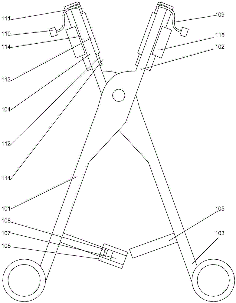
[0023] Such as figure 1 As shown, a general surgery flushing device includes a left forceps handle 101, a right forceps head 102 connected to the left forceps handle 101, a right forceps handle 103, and a left forceps head 104 connected to the right forceps handle 103. The left pliers handle 101 and the right pliers handle 103 are hinged to each other through pin shafts, and locking strips 105 are respectively arranged on the opposite surfaces of the left pliers handle 101 and the right pliers handle 103, and the Threads are respectively provided on the locking bars 105 of the left pliers handle 101, an annular groove 108 is arranged on the locking bars 105 on the left pliers handle 101, and an annular groove 108 is arranged on the locking bars 105 on the left pliers handle 101. A fixed rod 106 is provided, and the fixed rod 106 is engaged in the annular groove 108 and can rotate around the axis of the annular groove 108. When the fixed rod 106 is far away from the One end of...

Embodiment 2

[0026] In this embodiment, on the basis of Embodiment 1, in order to facilitate the installation of the guide tube, preferably, snap-fitting parts 111 are respectively provided on the guide tube 109, and the guide tube 109 respectively passes through the The locking part 111 is set in the through hole. By arranging the clamping part structure, it is possible to realize the fixing of the guide tube relative to the through hole, improve the stability of the structure, and prevent the guide tube from falling off during suction.

[0027] In order to improve the flushing efficiency, in this embodiment, it is further preferred that diversion grooves 112 are respectively arranged on the opposite surfaces of the left pliers head 104 and the right pliers head 102, and the flow diversion grooves 112 are respectively It is arranged along the length direction of the left pliers head 104 and the right pliers head 102 , and the through hole communicates with the flow guiding groove 112 . B...


PUM


Abstract

The invention discloses a flushing device for general surgery department. The flushing device comprises a left tong arm, a right tong head connected to the left tong arm, a right tong arm and a left tong head connected to the right tong arm, wherein the left tong arm and the right tong arm are mutually hinged by virtue of a pin shaft; locking strips are respectively arranged on opposite surfaces of the left tong arm and the right tong arm; the end, away from the pin shaft, of the left tong head and the end, away from the pin shaft, of the right tong head are provided with through holes; stream guidance tubes are arranged inside the through holes; the stream guidance tubes are made from medical silica gel; the end, away from the corresponding through hole, of each of the stream guidance tubes is provided with a seal cover; and suction ports are arranged on the seal covers. The flushing device disclosed by the invention, by virtue of the locking devices, is conducive to the fixation of the integral structure; meanwhile, by adopting two stream guidance tubes, flushing for an operative site and suction for liquid are conveniently implemented; and the flushing device is simple to operate, and operation steps are effectively simplified, and operation efficiency is improved.

Description

technical field [0001] The invention relates to a flushing device for general surgery. Background technique [0002] When cleaning the surgical site during general surgery, it is usually necessary to use a special person to grasp the cleaning equipment and at the same time have a special person suck the liquid. The operation is cumbersome and wastes manpower. Contents of the invention [0003] The purpose of the present invention is to provide a flushing device for general surgery, which can improve the problems existing in the prior art. By adopting a locking device, it is helpful to fix the overall structure, and at the same time, two drainage tubes are used to realize the flushing of the surgical site And the suction of the liquid, the operation is simple, the operation steps can be effectively saved, and the operation efficiency can be improved. [0004] The present invention is realized through the following technical solutions: [0005] A flushing device for genera...

Claims


Application Information

Patent Timeline
Patent Type & Authority Applications(China)
IPC IPC(8): A61M3/02A61M1/00
CPCA61M3/0283A61M1/0023A61M1/0058
Inventor 李林浩张倩肖永来张琳
Owner 李林浩
Why Eureka
Try Eureka