Ultrahigh-purity gas dilution system

A pure gas, ultra-high technology, applied in the direction of gas and gas/steam mixing, mixer, mixing method, etc., to reduce the risk of uneven gas mixing, increase outlet pressure, and expand the range of dilution ratio

Inactive Publication Date: 2016-03-16
NAT INST OF METROLOGY CHINA
View PDF4 Cites 4 Cited by
  • Summary
  • Abstract
  • Description
  • Claims
  • Application Information

AI Technical Summary

Problems solved by technology

[0004] The object of the present invention is to provide an ultra-high-purity gas dilution system to solve the above-mentioned problems that arise when the gas is diluted by a dynamic method

Method used


Image

  • Ultrahigh-purity gas dilution system
  • Ultrahigh-purity gas dilution system
  • Ultrahigh-purity gas dilution system

Examples


Embodiment 1

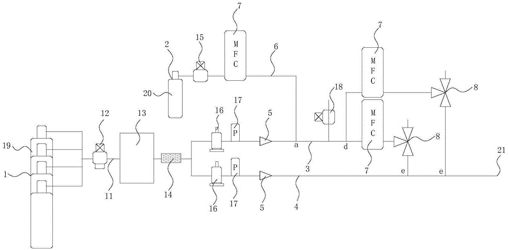
[0022] In this embodiment, an ultra-high-purity gas dilution system is provided, which is used to dilute the existing gas standard with higher concentration to a gas standard with lower concentration, such as figure 1 As shown, it includes a dilution gas source 1 and a gas to be diluted source 2, wherein the dilution gas source 1 contains a dilution gas, and the gas to be diluted source 2 contains a gas to be diluted. In this embodiment, through multiple mixing and dilution of the above two gases, a gas standard that meets the requirements is finally obtained.

[0023] The dilution gas source 1 is connected with a first dilution gas pipeline 3 and a second dilution gas pipeline 4, which divide the dilution gas in the dilution gas source 1 into two paths for subsequent dilution; specifically, the dilution gas A pipeline 11 is arranged between the source 1 and the first diluent gas pipeline 3 and the second diluent gas pipeline 4, and the diluent gas in the diluent gas source 1 ...

Embodiment 2

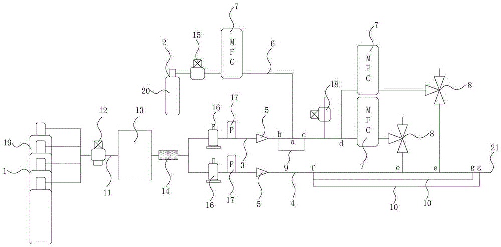
[0058] This embodiment is improved on the basis of embodiment 1, specifically:

[0059] Such as figure 2 As shown, in this embodiment, at least one first branch pipeline 9 is provided on the first dilution gas pipeline 3, and the communication point a between the gas pipeline to be diluted 6 and the first dilution gas pipeline 3 is located in the first branch pipeline 9 and the two connection points b and c of the first dilution gas pipeline 3, in this embodiment, the connection point between the inlet of the first branch pipeline 9 and the first dilution gas pipeline 3 is set as the connection point b, The connection point between the outlet of the first branch pipeline 9 and the first dilution gas pipeline 3 is set as a connection point c, and the connection point a is located between the connection point b and the connection point c. When multiple first branch pipelines 9 are set, the outer first branch pipeline 9 wraps the inner first branch pipeline 9, and the connectio...


PUM


Abstract

The invention discloses an ultrahigh-purity gas dilution system. The ultrahigh-purity gas dilution system comprises a diluting gas source and a gas-to-be-diluted source, the diluting gas source is connected with a first diluting gas pipeline and a second diluting gas pipeline, the second diluting gas pipeline is connected with an outlet, the first diluting gas pipeline and the second diluting gas pipeline are respectively provided with a sonic nozzle, the gas-to-be-diluted source is connected with the first diluting gas pipeline through a gas-to-be-diluted pipeline, the gas-to-be-diluted pipeline is provided with a mass flow controller, and the first diluting gas pipeline is connected with at least one shunting dilution device connected with the second diluting gas pipeline. The mass flow controller, the sonic nozzles and the at least one diluting pipelines are arranged to continuously change the dilution concentration of a gas and improve the outlet pressure. Shunting and multi-time dilution are carried out through the at least one shunting dilution device, so the diluting proportion range is enlarged under a constant flow, the consumption of the diluting gas is saved, and large scale dilution is also reached.

Description

technical field [0001] The invention relates to the technical field related to gas dilution, in particular to an ultra-high-purity gas dilution system. Background technique [0002] In the electronics industry such as electronic semiconductors, the quality requirements of ultra-high-purity gases used in them are extremely high. For example, nitrogen, argon, and helium used for protective gas require their impurity content to be within 1×10 -9 mol / mol, so the impurity content of the above-mentioned gases needs to be tested before use to make them meet the requirements. Since the detection limit of conventional gas analysis instruments is generally 10×10 -9 mol / mol or more, it cannot satisfy the detection of impurity content in ultra-high-purity gas. Therefore, an atmospheric pressure ion mass spectrometer with higher sensitivity is required to detect the impurity content of ultra-high-purity gas. However, the atmospheric pressure ion mass spectrometer can only give the dete...

Claims


Application Information

Patent Timeline
Patent Type & Authority Applications(China)
IPC IPC(8): B01F3/02B01F15/04B01F23/10
CPCB01F23/19B01F35/83
Inventor 胡树国张体强
Owner NAT INST OF METROLOGY CHINA
Why Eureka
Try Eureka