An Ultra High Purity Gas Dilution System

A pure gas, ultra-high technology, used in gas and gas/vapor mixing, mixers, mixing methods, etc., to save consumption, expand the range of dilution ratios, and increase outlet pressure.

Inactive Publication Date: 2018-01-05
NAT INST OF METROLOGY CHINA
View PDF4 Cites 0 Cited by
  • Summary
  • Abstract
  • Description
  • Claims
  • Application Information

AI Technical Summary

Problems solved by technology

[0004] The object of the present invention is to provide an ultra-high-purity gas dilution system to solve the above-mentioned problems that arise when the gas is diluted by a dynamic method

Method used


Image

  • An Ultra High Purity Gas Dilution System
  • An Ultra High Purity Gas Dilution System
  • An Ultra High Purity Gas Dilution System

Examples


Embodiment 1

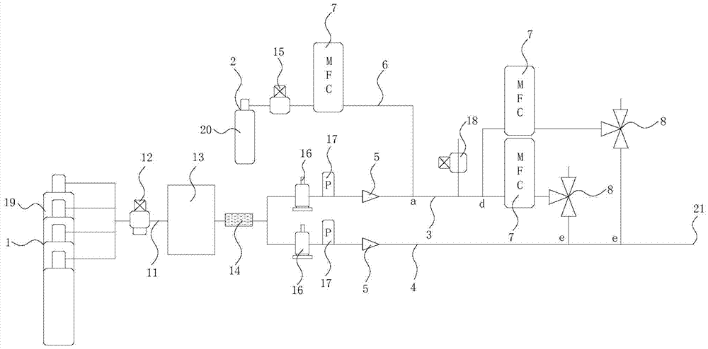
[0022] This embodiment provides an ultra-high-purity gas dilution system for diluting an existing gas standard with a higher concentration into a gas standard with a lower concentration, such as figure 1 As shown, it includes a dilution gas source 1 and a to-be-diluted gas source 2, wherein the dilution gas source 1 contains the dilution gas, and the to-be-diluted gas source 2 contains the gas to be diluted. In this embodiment, the gas standard that meets the requirements is finally obtained through multiple mixing and dilution of the above two gases.

[0023] The dilution gas source 1 is connected with the first dilution gas pipeline 3 and the second dilution gas pipeline 4, and the dilution gas in the dilution gas source 1 is divided into two paths for transportation for subsequent dilution; A pipeline 11 is set between the source 1 and the first diluent gas pipeline 3 and the second diluent gas pipeline 4, and the diluent gas in the diluent gas source 1 is transported to th...

Embodiment 2

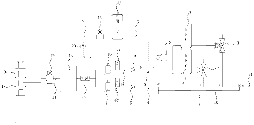
[0058] This embodiment is improved on the basis of Embodiment 1, specifically:

[0059] like figure 2 As shown, in this embodiment, at least one first branch pipeline 9 is provided on the first dilution gas pipeline 3, and the communication point a between the gas pipeline 6 to be diluted and the first dilution gas pipeline 3 is located in the first branch pipeline 9 and the two communication points b and c of the first dilution gas pipeline 3, in this embodiment, the connection point between the inlet of the first branch pipeline 9 and the first dilution gas pipeline 3 is set as the communication point b, The communication point between the outlet of the first branch pipe 9 and the first dilution gas pipe 3 is set as the communication point c, and the communication point a is located between the communication point b and the communication point c. When there are multiple first branch pipelines 9, the first branch pipeline 9 on the outside wraps the first branch pipeline 9 o...


PUM


Abstract

The invention discloses an ultra-high-purity gas dilution system, which includes a dilution gas source and a gas source to be diluted. The dilution gas source is connected with a first dilution gas pipeline and a second dilution gas pipeline, and the second dilution gas pipeline is connected with The outlet, the first dilution gas pipeline and the second dilution gas pipeline are equipped with sonic nozzles, the source of the gas to be diluted is connected to the first dilution gas pipeline through the gas pipeline to be diluted, and the pipeline of the gas to be diluted is equipped with mass flow control The first dilution gas pipeline communicates with at least one split flow dilution device communicating with the second dilution gas pipeline. The invention can not only continuously change the dilution concentration of the gas but also increase the outlet pressure by setting a mass flow controller, a sonic nozzle and a plurality of dilution pipelines. Divided flow and multiple dilutions are carried out by the separation and dilution device, which realizes the expansion of the dilution ratio range under a certain flow rate, which not only saves the consumption of dilution gas, but also achieves the purpose of large-scale dilution.

Description

technical field [0001] The invention relates to the related technical field of gas dilution, in particular to an ultra-high-purity gas dilution system. Background technique [0002] In the electronic industry such as electronic semiconductors, the quality requirements of the ultra-high-purity gases used are extremely high. For example, nitrogen, argon and helium used for shielding gas are required to have an impurity content of 1×10 -9 mol / mol or less, so the impurity content of the above gas needs to be tested before use to make it meet the requirements. Since the detection limit of conventional gas analysis instruments is generally 10 × 10 -9 Above mol / mol, it cannot meet the detection of impurity content of ultra-high-purity gas. Therefore, to detect the impurity content of ultra-high-purity gas, atmospheric pressure ion mass spectrometer with higher sensitivity is required. However, atmospheric pressure ion mass spectrometer can only provide detection when detecting I...

Claims


Application Information

Patent Timeline
Patent Type & Authority Patents(China)
IPC IPC(8): B01F3/02B01F15/04B01F23/10
CPCB01F23/19B01F35/83
Inventor 胡树国张体强
Owner NAT INST OF METROLOGY CHINA
Why Eureka
Try Eureka