A drilling device for measuring residual stress by blind hole method

A residual stress, drilling device technology, applied in the direction of boring/drilling, drilling/drilling equipment, components of boring machine/drilling machine, etc., can solve the difficulty of drilling, difficult to control the size of the pressure, and slow drilling speed and other problems, to achieve the effect of intuitively aligning the drilling position, saving labor and making the operation more convenient, and improving the drilling accuracy.

Active Publication Date: 2017-11-17
CENT SOUTH UNIV
View PDF5 Cites 0 Cited by
  • Summary
  • Abstract
  • Description
  • Claims
  • Application Information

AI Technical Summary

Problems solved by technology

When the hardness of the material is high, as the drilling depth increases, the resistance to the rotation of the drill bit gradually increases, making drilling more difficult
Usually the counterweight is only suitable for drilling vertically downwards. It is often difficult to control the pressure when directly applying pressure to the drilling rig. The drilling speed is often too slow when the pressure is too small. Human error, labor and time consuming

Method used


Image

  • A drilling device for measuring residual stress by blind hole method
  • A drilling device for measuring residual stress by blind hole method
  • A drilling device for measuring residual stress by blind hole method

Examples


Embodiment Construction

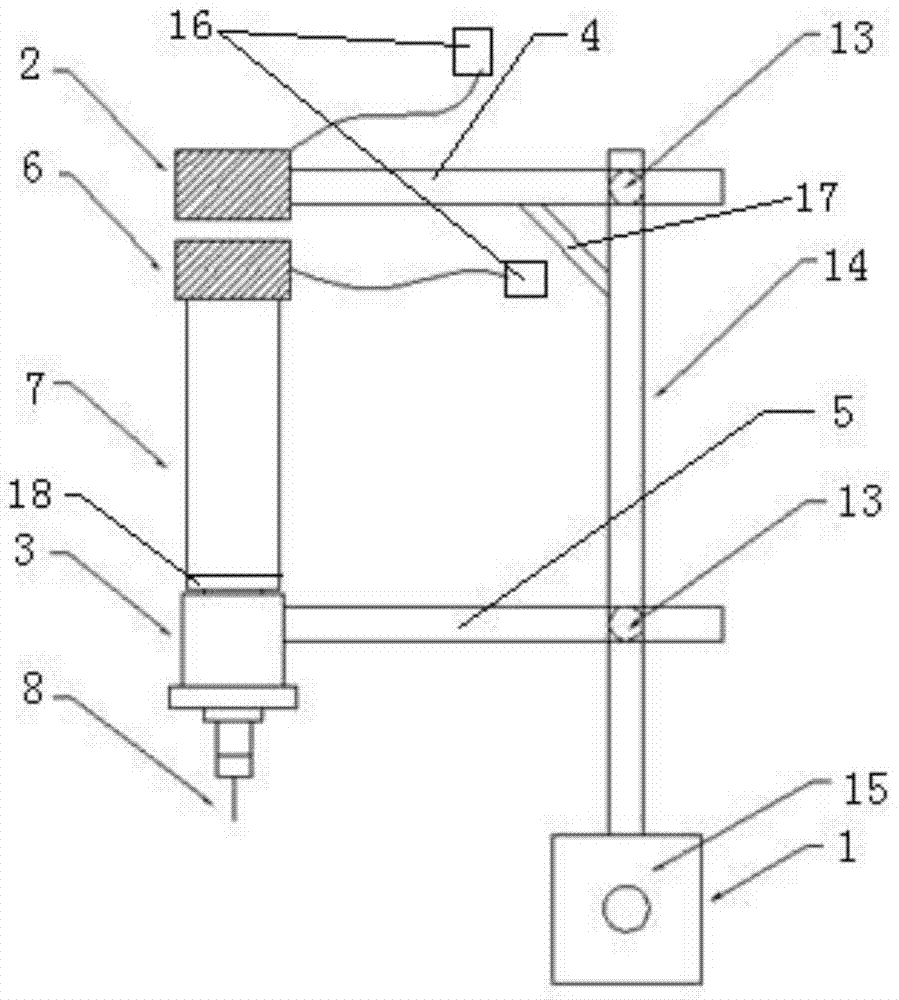
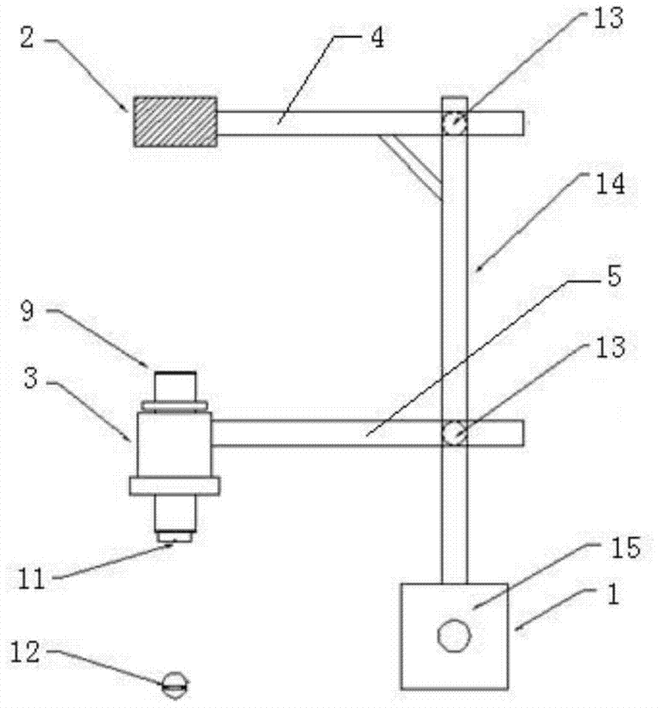
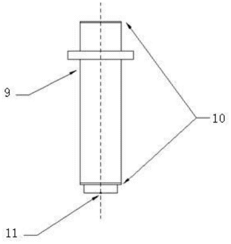
[0028] like Figure 1-5 As shown, the present invention provides a drilling device for measuring residual stress by blind hole method, comprising an I-shaped support, the support includes an upper beam 4, a lower beam 5 and a vertical rod 14, and the upper beam 4 and the lower beam 5 pass through the steering bolts 13 is connected to the two ends of the vertical rod 14, and the lower end of the vertical rod 14 is provided with a support base 1; one end of the lower beam 5 is fixedly connected with a guide sleeve 3, and when the drilling position needs to be positioned, the guide sleeve 3 is provided with an alignment device , when drilling is required, a drill is provided in the guide sleeve 3, and the drill includes a drill sleeve 7 arranged on the guide sleeve 3. The bottom end of the drill sleeve 7 is provided with a drill bit 8, and the drill bit 8 passes through the In the guide sleeve 3, a continuous force device is provided between the top of the drill sleeve 7 and the ...


PUM


Abstract

The invention provides a drilling device for measuring residual stress through a blind hole method. The drilling device comprises an I-shaped support. The support comprises an upper cross beam, a lower cross beam and a vertical rod. The upper cross beam and the lower cross beam are connected to the two ends of the vertical rod through reversing bolts. A supporting base is arranged at the lower end of the vertical rod. A guide sleeve is fixedly connected to one end of the lower cross beam. An alignment device or a driller is arranged in the guide sleeve. The driller comprises a drilling cylinder sleeve which is arranged on the guide sleeve. A drill bit is arranged at the bottom end of the drilling cylinder sleeve and penetrates through the guide sleeve. A continuous force application device is arranged between the top end of the drilling cylinder sleeve and the upper cross beam and comprises an electromagnetic pressure block arranged at the top end of the drilling cylinder sleeve and an electromagnetic counter-force block which is arranged at one end of the upper cross beam and matched with the electromagnetic pressure block. The drilling device is simple in structure, convenient to operate and capable of saving time and labor and achieving the effects of improving the drilling precision and increasing the drilling speed, and the problems that it is difficult to guarantee the precision during drilling, and force application is difficult are solved.

Description

technical field [0001] The invention relates to the technical field of drilling tools, in particular to a drilling device for measuring residual stress by a blind hole method. Background technique [0002] During mechanical processes such as welding, cutting, and installation, it is often easy to cause plastic deformation of the material and cause residual stress in the workpiece. During the service process of the workpiece, the residual stress and the working stress generated by the external load are superimposed on each other, which will cause stress redistribution and secondary deformation of the workpiece. The residual stress may not only reduce the stiffness and stability of the workpiece, but also seriously affect the fatigue life of the structure. And the ability to resist stress corrosion, thus affecting the normal performance of the workpiece. Therefore, the testing and impact assessment of residual stress is particularly important. [0003] Residual stress testin...

Claims


Application Information

Patent Timeline
Patent Type & Authority Patents(China)
IPC IPC(8): B23B39/00B23B47/00B23B49/02
CPCB23B39/00B23B47/00B23B49/02
Inventor 卫军汪东明刘晓春董荣珍吴志强陈涛
Owner CENT SOUTH UNIV
Why Eureka
Try Eureka