Finish-milling tool and method used for hub surface machining

A hub surface, fine milling technology, applied in the direction of milling cutters, manufacturing tools, metal processing equipment, etc., can solve the problems of slow processing efficiency, high processing speed, fire caused by high temperature, processing time, safety, high processing cost, etc., to prevent adhesion , Reduce processing costs and the effect of safety performance

Inactive Publication Date: 2016-03-16
TAIAN QICHENG WHEEL MFG
View PDF8 Cites 5 Cited by
  • Summary
  • Abstract
  • Description
  • Claims
  • Application Information

AI Technical Summary

Benefits of technology

This invention relates to an improved method for machining materials with precise tools that have very small teeth or blades attached at their ends instead of traditional sharp edges made up entirely of metal. By having these tiny parts inside the machine's cutter head, they are protected against damage during use without requiring excessive coolant usage. Additionally, there can be fewer steps needed when replacing worn out bits compared to other methods like laser drilling. Overall this technology reduces costs while improving efficiency and security over existing techniques.

Problems solved by technology

The technical problem addressed by this patented technology relates to improving the quality of machined surfaces made from aluminium alloys during manufacturing without causing damage such as scratches that may affect their appearance when they come into contact with other objects like metal plating layers. This requires specialized equipment called grinding tools and cleaners specifically tailored towards specific areas where there will occur corrosion issues due to exposure to acidic environments caused by various chemicals present inside the vehicle's body.

Method used


Image

  • Finish-milling tool and method used for hub surface machining
  • Finish-milling tool and method used for hub surface machining

Examples


Embodiment Construction

[0023] The following will clearly and completely describe the technical solutions in the embodiments of the present invention with reference to the accompanying drawings in the embodiments of the present invention. Obviously, the described embodiments are only some, not all, embodiments of the present invention. Based on the embodiments of the present invention, all other embodiments obtained by persons of ordinary skill in the art without making creative efforts belong to the protection scope of the present invention.

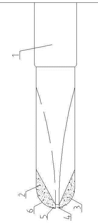
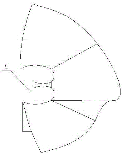
[0024] A fine milling tool for surface machining of hubs, figure 1 It is the first embodiment of the present invention. This embodiment will be described in detail in conjunction with the accompanying drawings. It includes a cutter body 1, a diamond blade I2 and a diamond blade II3. The cutting end of the cutter body 1 is provided with a diamond blade I2 and a diamond blade II3. Moreover, the diamond blade I2 and the diamond blade II3 are arranged in a gap dis...


PUM

PropertyMeasurementUnit
Widthaaaaaaaaaa

Abstract

The invention discloses a finish-milling tool and method used for hub surface machining. The finish-milling tool comprises a finish-milling tool body provided with a cutter body (1) and a diamond edge body, wherein the diamond edge body is arranged on a cutting end face part of the cutter body (1) and provided with a chip discharging channel. Extrusion machining is conducted on the hub surface through the diamond edge body, and a bright surface is formed on the hub surface; through the heat dissipation effect of the chip discharging channel of the diamond edge body, the situation that cutting chips adhere to the diamond edge body due to high temperature is prevented, and no cutting liquid is needed, so that the machining cost is reduced, and the safety performance is improved.

Description


Claims


Application Information

Patent Timeline
Owner TAIAN QICHENG WHEEL MFG
Why Eureka
Try Eureka