A three-dimensional printing device

A 3D printing and printing head technology, applied in the field of 3D printing, can solve the problems of limited "support" bearing capacity, multi-material and printing time, product collapse, etc., to reduce the risk of collapse, improve printing efficiency, and eliminate delamination Effect

Active Publication Date: 2017-07-11
台州新森增材制造有限公司
View PDF6 Cites 0 Cited by
  • Summary
  • Abstract
  • Description
  • Claims
  • Application Information

AI Technical Summary

Problems solved by technology

However, every time a "support" is printed, more materials and printing time will be consumed, and the carrying capacity of the "support" is also limited (to ensure that the "support" is easy to separate and remove), if the support is high and large, it is easy to cause Partial collapse or even damage of the product
However, the current 3D printing equipment is still lacking in terms of saving "support" volume and quantity, improving printing efficiency and printing process stability, etc.

Method used


Image

  • A three-dimensional printing device
  • A three-dimensional printing device
  • A three-dimensional printing device

Examples


Embodiment 1

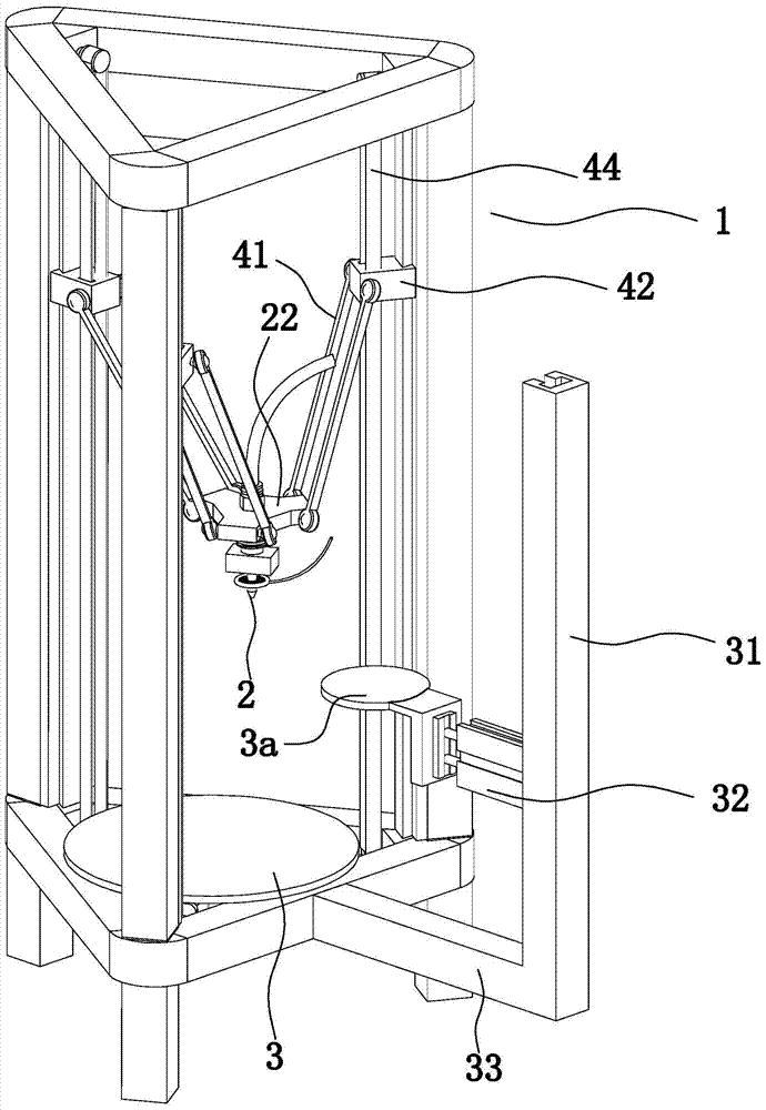
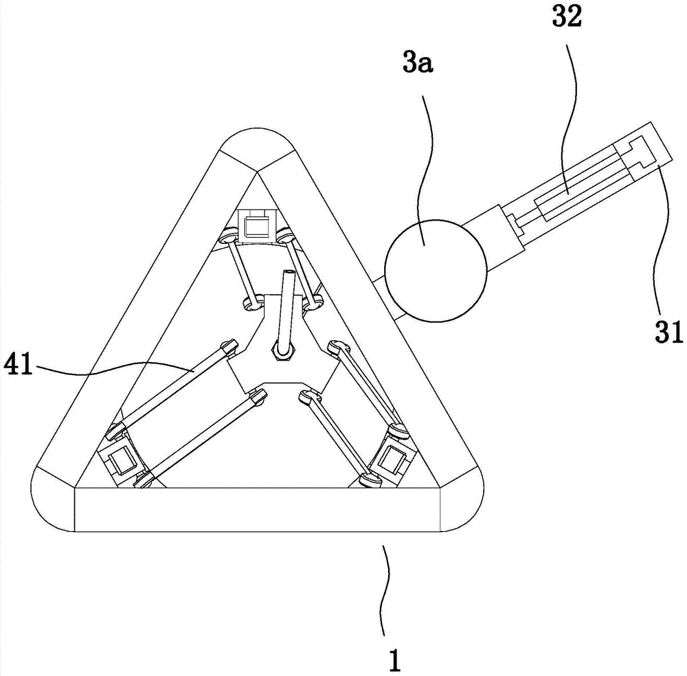
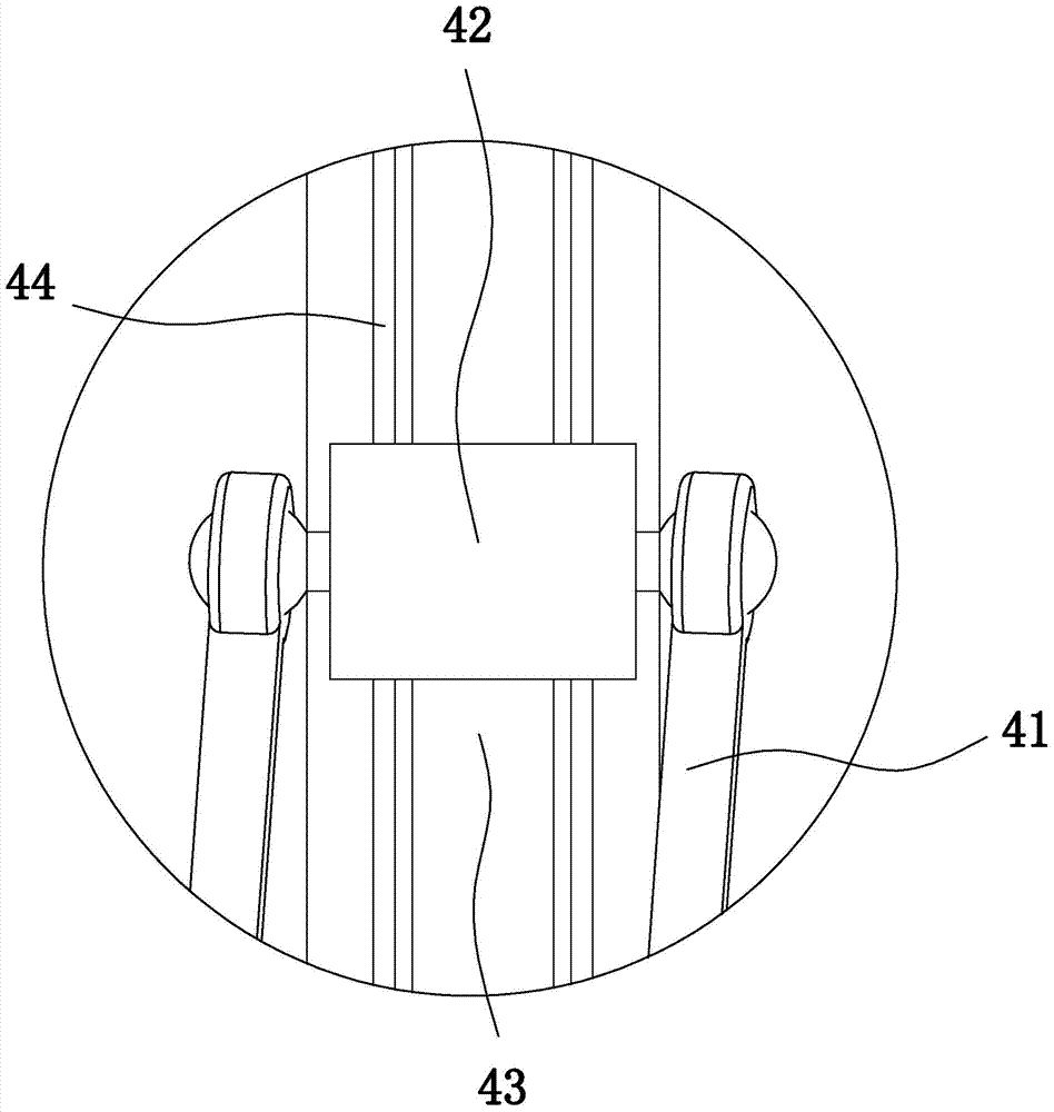
[0028] Example 1: as Figure 1 to Figure 6 In the embodiment shown, a three-dimensional printing device includes a main frame 1, a discharge printing head 2, a forming printing platen 3 in the main frame, and a three-dimensional printing device for driving the discharge printing head to move to change the output. A print head displacement adjustment mechanism for the position of the print head, the discharge print head is provided with a print head feed end for inputting printing raw materials, and the discharge print head is provided with a discharge that communicates with the feed end of the print head The channel 21 also includes at least one side support platen 3a, at least one side support and driving structure that can drive the side support platen into the area directly above the forming printing platen, and the side support platen and the side support and driving structure correspond one-to-one. When the side support platen enters (is in) the range directly above the f...

Embodiment 2

[0035] Embodiment 2: In this embodiment, the servo cylinder in Embodiment 1 is replaced by an air cylinder / oil cylinder / servo cylinder. Whether it is an air cylinder, oil cylinder, servo cylinder, or servo cylinder, as long as the height adjustment of the movable platen can be achieved, any other commonly used adjustment mechanisms, such as screw mechanisms, can also be selected.

Embodiment 3

[0036] Embodiment 3: The basic structure and implementation of this embodiment are the same as those of Embodiment 1, and the difference lies in:

[0037] like Figure 7 As shown in , the discharge channel is provided with a heat insulation cylinder 23 coaxial with the discharge channel, the upper and lower ends of the heat insulation cylinder are open, the heat insulation cylinder is connected with the discharge print head through a connecting rod, and the outside of the heat insulation cylinder is A thin material coloring channel 24 is formed between the wall and the channel wall of the discharge channel (that is, the inner wall of the discharge print head). The coloring tube outlet faces the outer wall of the heat insulation cylinder. The coloring tube outlet is provided with a coloring check valve 521. The passing direction of the coloring check valve is from the coloring pipe to the discharge channel. The vertical distance between the lower end of the heat insulating cyl...


PUM


Abstract

The invention discloses a three-dimensional printing device. The three-dimensional printing device comprises a main rack, a discharging printing head and a forming printing table plate located in the main rack. The three-dimensional printing device further comprises a printing head displacement adjusting mechanism used for driving the discharging printing head to move so as to change the position of the discharging printing head. The discharging printing head is provided with a printing head feeding end used for inputting printing raw materials. A discharging channel communicated with the printing head feeding end is arranged in the discharging printing head. The three-dimensional printing device further comprises at least one side supporting table plate and at least one side supporting driving structure driving the side supporting table plate to enter the range over the forming printing table plates. The side supporting table plates correspond to the side supporting driving structures in a one-to-one manner. The three-dimensional printing device has the beneficial effects that the structure is reasonable, adjustment can be carried out according to supporting requirements, auxiliary supporting (non-printing supporting) is flexibly provided, and the original printing supporting requirement is lowered accordingly; and the printing efficiency can be improved, the risks of local collapsing of products is reduced, supporting materials are saved, and product stability in the printing process can be guaranteed.

Description

technical field [0001] The invention belongs to the technical field of 3D printing, and in particular relates to a three-dimensional printing device. Background technique [0002] 3D printer, also known as three-dimensional printer (3DP), is a machine that uses cumulative manufacturing technology, that is, rapid prototyping technology. 3D printing technology is based on a digital model file. It uses adhesive materials such as molten plastic to create three-dimensional objects by printing layers of adhesive materials, that is, the technology of constructing objects by layer-by-layer printing. At this stage, 3D printers are mostly used to manufacture products. [0003] The 3D printer mainly includes a printing structure (print head), a forming printing platen (on which the product is formed) and a printing head displacement adjustment mechanism (which can spatially change the position of the printing head, so that the printed raw materials can fall on the forming printing tab...

Claims


Application Information

Patent Timeline
Patent Type & Authority Patents(China)
IPC IPC(8): B29C64/20B29C64/245B33Y30/00
CPCB29C67/00
Inventor 唐乔邵永新许启明陆柽齐吴钍荣
Owner 台州新森增材制造有限公司
Why Eureka
Try Eureka