A ring track laminating machine

A laminator and ring-rail type technology, applied in the field of ring-rail type laminators, can solve the problems of low degree of automation, reduced work efficiency, film breaking, etc., and achieve high degree of automation, simple and compact structure, and improved production efficiency. Effect

Active Publication Date: 2017-08-15
HEFEI GENERAL MACHINERY RES INST
View PDF6 Cites 0 Cited by
  • Summary
  • Abstract
  • Description
  • Claims
  • Application Information

AI Technical Summary

Problems solved by technology

This type of winding laminating machine has two disadvantages. One is that when the packaged product is relatively large and heavy, the rotational speed will be limited to a certain extent when rotating the product for laminating and packaging, that is, it can only work at low speed, and the working efficiency will be limited. At the same time, due to the rotation of heavy-duty products, the driving power will also increase, and the energy consumption will be high, which is not conducive to energy saving; secondly, the packaged products are generally transported to and removed from the turntable by forklifts, which has a low degree of automation and is difficult to use online Used for packaging products, it cannot improve the automation level of the enterprise production line, let alone realize unmanned packaging operations
[0004] In addition, the film release device in the prior art is mainly operated by an ordinary motor, which cannot meet the standard in tension control. If the film discharge motor speed is slow, the film may be pulled off; if the film discharge motor speed is fast, the film may also Very loose and cannot cover around the product

Method used


Image

  • A ring track laminating machine
  • A ring track laminating machine
  • A ring track laminating machine

Examples


Embodiment Construction

[0081] The technical solutions in the present invention will be clearly and completely described below in conjunction with the accompanying drawings in the embodiments of the present invention. Based on the embodiments of the present invention, all other embodiments obtained by persons of ordinary skill in the art without making creative efforts belong to the protection scope of the present invention.

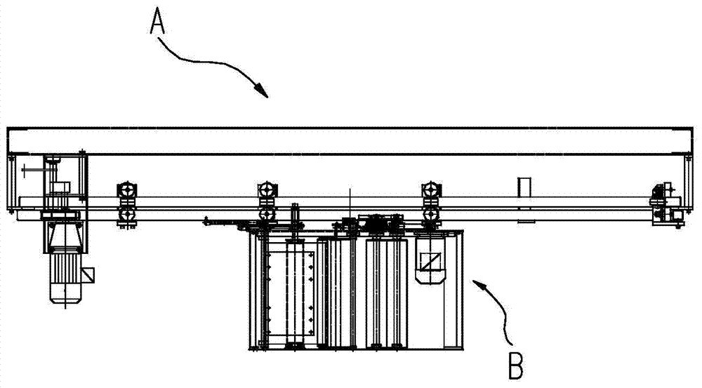
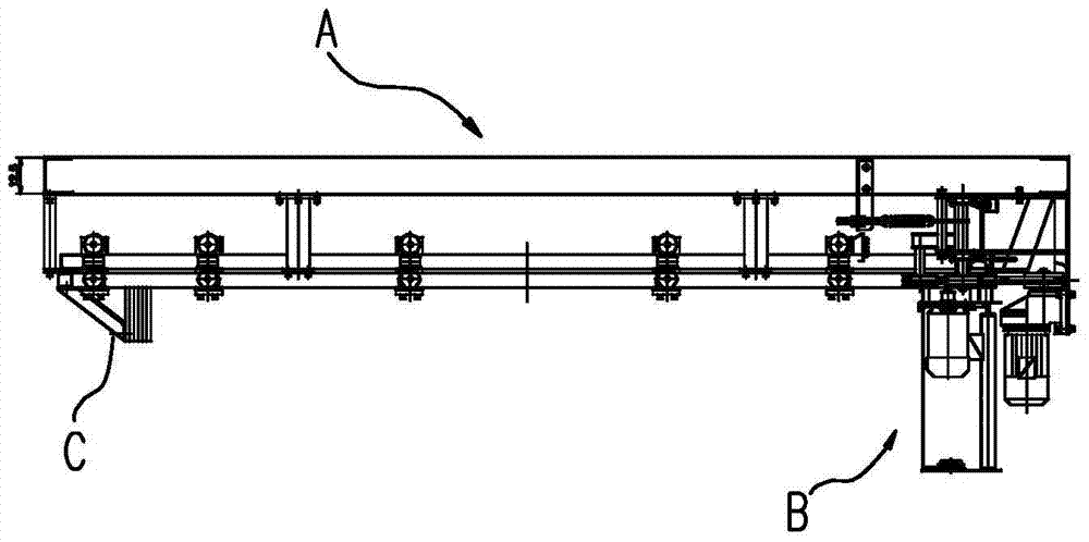
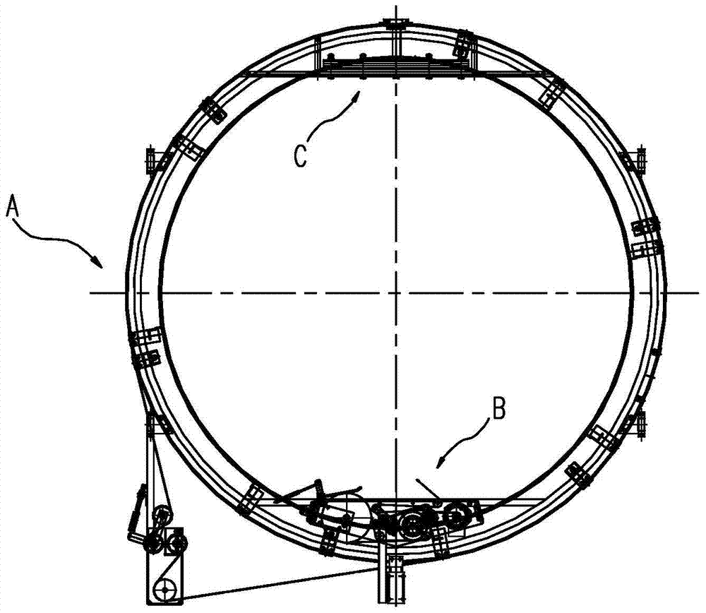
[0082] Such as Figure 1~3 As shown, it is a ring track type laminating machine. The laminating machine includes a transmission device A and a film release control device B. The film release control device B is fixed on the transmission device A and rotates with the transmission device A.

[0083] Transmission A

[0084] Such as Figure 4~6 As shown, it is a transmission device for a ring-rail laminating machine, including a platform frame A1, and the lower part of the platform frame A1 is provided with a connecting hanger A10 for easy fixing. The driving device A2 at the bo...


PUM


Abstract

The invention discloses a circular track type film laminating machine. The circular track type film laminating machine comprises a transmission device and a film feeding control device which achieve automatic film laminating. The film feeding control device is fixed to the transmission device and performs rotational motion along with the transmission device. The transmission device comprises a platform rack and further comprises a driving device, a track device and a power picking device, wherein connecting hangers convenient to fix are disposed under the platform rack; the driving device is mounted on the lower portion of the platform rack; the track device is fixedly connected to the lower side of the platform rack through the connecting hangers; the power picking device is disposed on the track device. The film feeding control device comprises a rack and further comprises a film storing mechanism and a film feeding mechanism which are fixedly arranged on the rack and sequentially connected, and a film is made to sequentially pass through the film storing mechanism and the film feeding mechanism to be delivered to a film clamping rod. During film laminating, an object does not rotate, and a film laminating mechanism rotates, so that the needed driving force is greatly reduced and the energy consumption is decreased. Meanwhile, the film feeding control device can make the film keep tensioned to a certain degree all the time, so that the film is not tightly tensioned and loosened, and the automation degree is high.

Description

technical field [0001] The invention belongs to the technical field of packaging machinery, and in particular relates to a ring track type laminating machine. Background technique [0002] Winding and laminating machine is a kind of packaging equipment that manufacturers use more. After the product is coated and packaged, it can not only protect the product from damage during transportation, but also avoid the influence of dust and moisture in the air on product quality. . The appearance of the product after film-coated packaging is beautiful and neat, which is more in line with people's aesthetics, which is conducive to product promotion and sales. At present, some metallurgical enterprises in China, such as copper material factories, generally require copper rod coils and copper plate coils to be packaged with outer film coating, because the moisture in the air can accelerate the oxidation of the copper surface, which is not conducive to the preservation and transportatio...

Claims


Application Information

Patent Timeline
Patent Type & Authority Patents(China)
IPC IPC(8): B65B11/02B65B41/12B65B65/02B65B57/04
CPCB65B11/025B65B41/12B65B57/04B65B65/02
Inventor 徐鹏戴远敬吴志荣韩占华郭飞纪克鹏张志伟
Owner HEFEI GENERAL MACHINERY RES INST
Why Eureka
Try Eureka