An electrospinning device with a tine cage electrode

A cage-shaped electrode and electrospinning technology, which is applied in textiles and papermaking, filament/thread forming, fiber processing, etc., can solve the problems of large contact area between spinning solution and air, difficulty in nozzle clogging, and difference in dripping and supplying liquid High spinning efficiency, low contact area and simple structure can be achieved

Active Publication Date: 2017-09-26
DONOGGUAN AIR GUARD MFG CO LTD
View PDF7 Cites 0 Cited by
  • Summary
  • Abstract
  • Description
  • Claims
  • Application Information

AI Technical Summary

Problems solved by technology

[0003] The industrial application of electrospinning nanofibers is inseparable from the mass production of electrospinning nanofibers. The current technology for mass production of nanofibers has multi-nozzle electrospinning devices. This method can realize mass electrospinning, but every The liquid supply of each nozzle varies greatly, and it is difficult to solve the problem of nozzle clogging and dripping; the first generation of spider spinning technology can realize mass production, and the output is relatively large, but its energy consumption is large, and it is used for spinning The contact area between the solution and the air is relatively large, resulting in inconsistent spinning quality before and after, so it has been eliminated by Ermark Company. The second-generation spider spinning technology solves the problem of solution volatility, but sacrifices the output. At the same time, there is an electrode wire Difficult to clean

Method used


Image

  • An electrospinning device with a tine cage electrode
  • An electrospinning device with a tine cage electrode
  • An electrospinning device with a tine cage electrode

Examples


Embodiment Construction

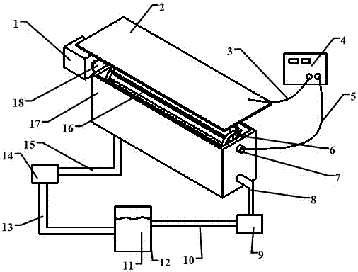
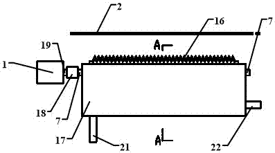
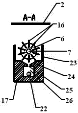
[0028] refer to Figure 1 to Figure 7 , which shows the specific structure of the preferred embodiment of the present invention. The structural characteristics of each element of the present invention will be described in detail below, and if there is a description of the direction (up, down, left, right, front and back), it is based on figure 1 The shown structure is a reference description, but the actual use direction of the present invention is not limited thereto.

[0029] The present invention provides an electrospinning device with a tine cage electrode, comprising a tine cage electrode, a power supply 4 and a collection device 2 arranged opposite to the tine cage electrode, and the tine cage electrode includes Two end plates and one or more canine linear electrodes 16 arranged between the two end plates, in the present invention, a plurality of canine linear electrodes 16 are preferably provided, and the canine linear electrodes 16 include linear A metal sheet whose ...


PUM


Abstract

The invention discloses an electrospinning device with a tine cage electrode, which comprises a tine cage electrode, a power supply and a collecting device. The tine cage electrode includes two end plates and one or more tine linear electrodes. A rotating shaft is arranged on the first end plate, and the tine linear electrode is provided with a number of tines equidistant from the axis of the rotating shaft and uniformly distributed on the edge of the side away from the rotating shaft. The power supply is electrically connected to the tine cage electrode and the collecting device respectively. Switching on the power creates the electric field required for the jet between each tine and the collection device. Using linear tine electrodes to combine tine cage electrodes, the structure is simple, easy to process, and it is easy to ensure that each electrode is installed on the same circle, thereby ensuring the uniformity of the electric field, and there are multiple straight lines between the two end plates In the case of straight tine electrodes, through the rotation of the shaft, one of the straight tine electrodes can be used to complete the uniform distribution of the solution on the other straight tine electrodes, so that the spinning work can continue and the spinning efficiency can be improved.

Description

technical field [0001] The invention is used in the technical field of electrospinning, and in particular relates to an electrospinning device with tine cage electrodes. Background technique [0002] At present, nanofibers have been widely used in environmental protection, biomedicine and other fields, and the most widely used technology for producing nanofibers is electrospinning technology. This technology relies on the action of a high-voltage electrostatic field to stretch and split the jet, and finally Method of forming nanofibers. [0003] The industrial application of electrospinning nanofibers is inseparable from the mass production of electrospinning nanofibers. The current technology for mass production of nanofibers has multi-nozzle electrospinning devices. This method can realize mass electrospinning, but every The liquid supply of each nozzle varies greatly, and it is difficult to solve the problem of nozzle clogging and dripping; the first generation of spider...

Claims


Application Information

Patent Timeline
Patent Type & Authority Patents(China)
IPC IPC(8): D01D5/00
Inventor 朱自明黄泽峰夏远祥梅晨黄深能江传玉黄冠成王圣王新力
Owner DONOGGUAN AIR GUARD MFG CO LTD
Why Eureka
Try Eureka