Glass fiber bobbin rest yarn removing device and control method thereof
A glass fiber yarn and bobbin technology, applied in the field of glass fiber bobbin residual yarn removal device, can solve the problems of low yarn cutting efficiency, poor yarn cutting effect, easy to cut bobbins, etc., and achieve good yarn cutting effect and not easy Cutting bobbins, high yarn cutting efficiency
- Summary
- Abstract
- Description
- Claims
- Application Information
AI Technical Summary
Problems solved by technology
Method used
Image

Examples
Embodiment 1
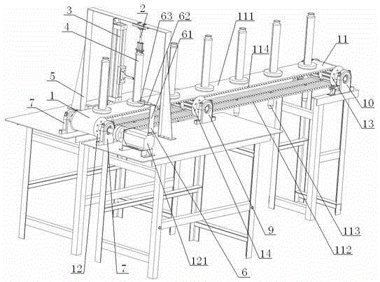
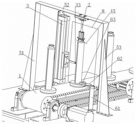
[0062] see Figure 1 to Figure 6 , a glass fiber bobbin remaining yarn removal device, comprising a bobbin conveying part 1, a bobbin rotating and positioning part 2, a glass fiber cutting part 3, the bobbin conveying part 1 includes a synchronous toothed belt 11, a No. 1 synchronous belt wheel 12, No. 2 synchronous pulley 13, the outer peripheral surface 111 of the synchronous toothed belt 11 is provided with bobbin installation pin 113 to cooperate with the bobbin 4, and the inner peripheral surface 112 of synchronous toothed belt 11 is provided with Belt teeth 114, one end inside the synchronous toothed belt 11 is provided with a No. 1 synchronous pulley 12 meshing with the toothed 114, and the other end inside the synchronous toothed belt 11 is provided with a No. 2 synchronous belt meshing with the toothed 114 wheel 13; the synchronous toothed belt 11 is provided with a bobbin 4, the bobbin 4 includes a bobbin body 41, both sides of the bobbin body 41 are provided with groo...
Embodiment 2
[0068] Basic content is the same as embodiment 1, the difference is:
[0069] see Figure 1 to Figure 6 , both sides of the No. 1 synchronous pulley 12 are provided with a No. 1 synchronous pulley mounting seat 7, and one end of the No. 1 synchronous pulley 12 is arranged in the No. 1 synchronous pulley mounting seat 7 on one side, and the No. 1 synchronous belt The other end of the wheel 12 is connected with one end of the No. 1 stepper motor 121 through the No. 1 synchronous pulley mount 7 on the other side; Seat 10, one end of the No. 2 synchronous pulley 13 is set in the No. 2 synchronous pulley mounting seat 10 on one side, and the other end of the No. 2 synchronous pulley 13 is set in the No. 2 synchronous pulley mounting seat 10 on the other side ; The inside of the synchronous toothed belt 11 is located at the position between the rotary cylinder bracket 5 and the second synchronous pulley 13. A synchronous belt tensioner 14 is provided, and the synchronous belt tensi...
Embodiment 3
[0072] Basic content is the same as embodiment 1, the difference is:
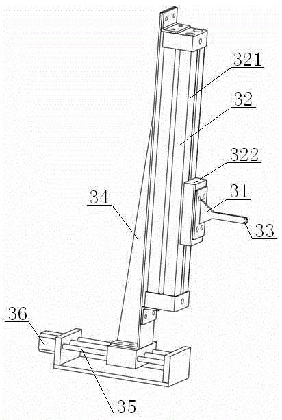
[0073] see Figure 1 to Figure 6 , the rodless cylinder 32 includes a cylinder body 321, a slider 322, one end of the slider 322 is connected with the cylinder body 321, and the other end of the slider 322 is connected with an end of the blade mount 31; the rodless cylinder 32 Set on the cylinder bracket 34, the lower end of the cylinder bracket 34 is set on the motion guide rail 35, and one end of the motion guide rail 35 is connected with No. 2 stepping motor 36.
[0074] According to the above scheme, in the second step of the control method, the No. 2 stepper motor 36 is first controlled to work so that the motion guide rail 35 works, and then the rodless cylinder 32 is controlled to move in a direction close to the bobbin 4 until the cutting blade 33 stretches out. Enter the groove 44 on the other side of the bobbin 4, and then control the cylinder body 321 of the rodless cylinder 32 to work, so that ...
PUM
 Abstract
Description
Claims
Application Information
 - R&D
- Intellectual Property
- Life Sciences
- Materials
- Tech Scout
- Unparalleled Data Quality
- Higher Quality Content
- 60% Fewer Hallucinations
Browse by: Latest US Patents, China's latest patents, Technical Efficacy Thesaurus, Application Domain, Technology Topic, Popular Technical Reports.
© 2025 PatSnap. All rights reserved.Legal|Privacy policy|Modern Slavery Act Transparency Statement|Sitemap|About US| Contact US: help@patsnap.com