Device for cutting residual yarn on the surface of spun bobbin and its control method
A cutting device and spun yarn bobbin technology, applied in the textile field, can solve the problems of low labor intensity for residual yarn removal, high labor intensity for residual yarn removal, and high scrap rate of spun yarn bobbins, and achieves improved yarn cutting effect, good yarn cutting effect, and reduced The effect of scrap rate
- Summary
- Abstract
- Description
- Claims
- Application Information
AI Technical Summary
Problems solved by technology
Method used
Image

Examples
Embodiment 1
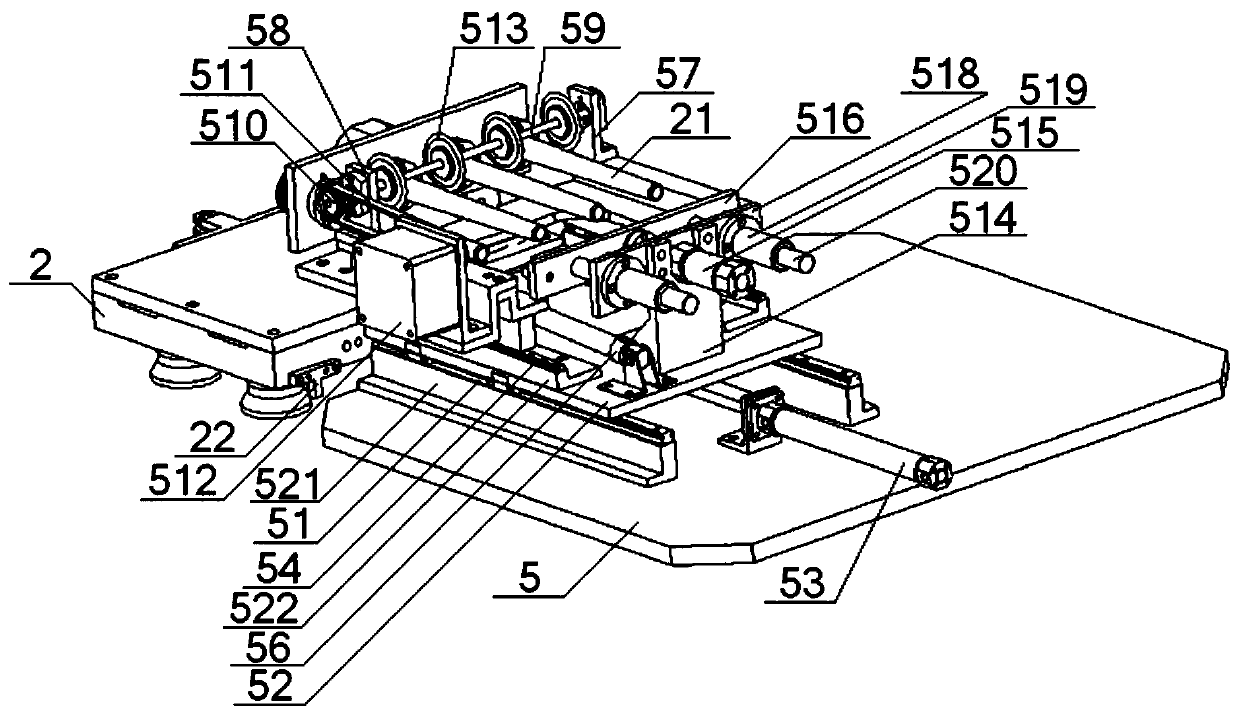
[0051] see Figure 1 to Figure 5 , a device for cutting residual yarn on the surface of a spun bobbin, comprising a circular guide rail 1 and a conveying trolley 2 slidingly connected thereon, a timing belt 3 is arranged on the inner side of the circular guide rail 1, and the synchronous belt 3 is connected with the conveying trolley 2, the The conveying trolley 2 is horizontally provided with a plurality of sleeves 21 for fitting the spun bobbins 4, the outer side of the annular guide rail 1 is located near the conveying trolley 2 and is provided with a mounting base plate 5, and two parallel tubes are arranged on the mounting base 5. No. 5 guide rail 51, a cutting platform 52 is slidably connected between the two No. 1 guide rails 51, and the cutting platform 52 is connected with the No. 1 cylinder 53. Two No. A moving base plate 55 is slidably connected between the guide rails 54, and the moving base plate 55 is connected with the No. 2 cylinder 56. The moving base plate 55...
Embodiment 2
[0054] Basic content is the same as embodiment 1, the difference is:
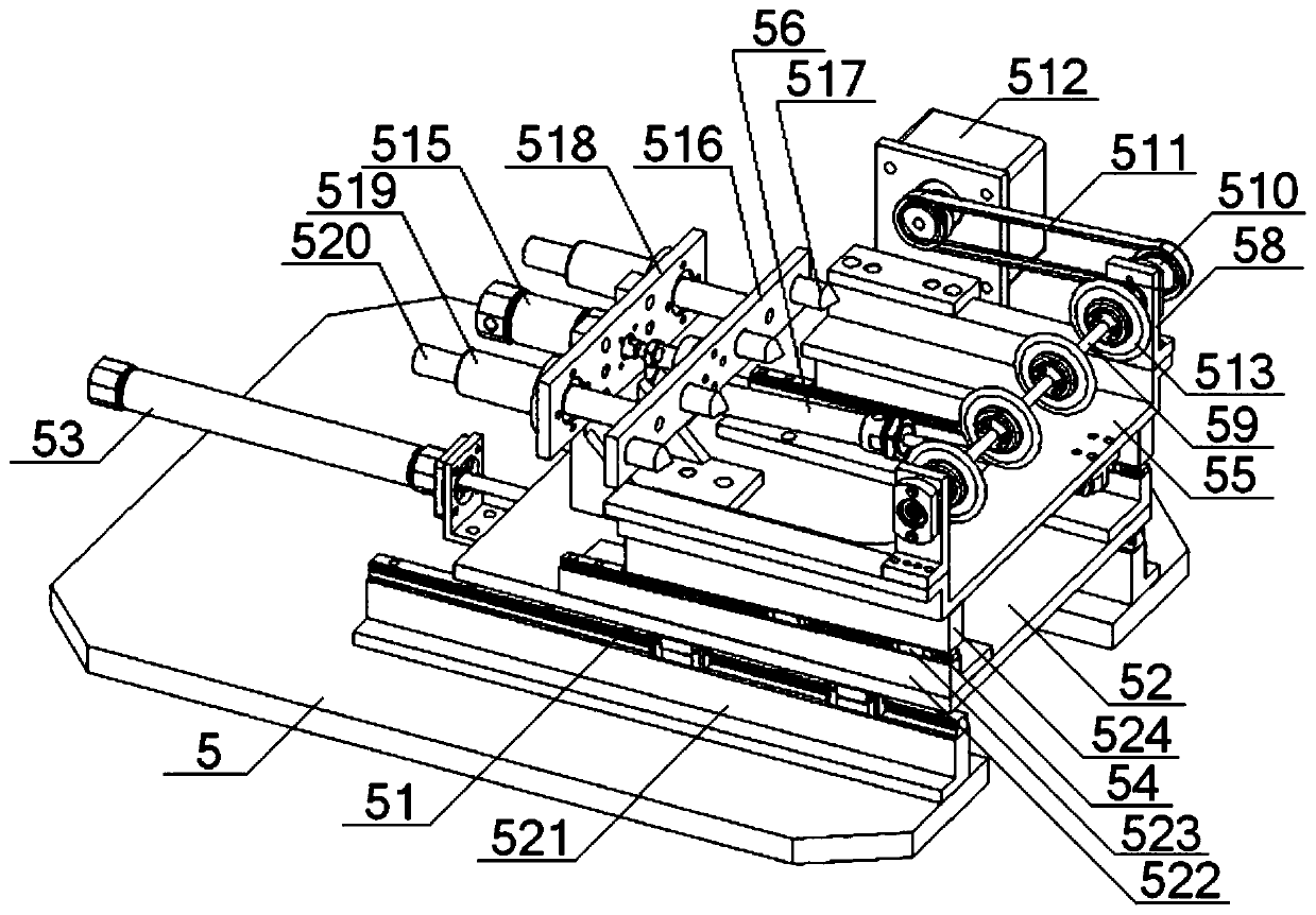
[0055] see figure 1 , figure 2 , the cutting platform 52 is provided with a top cone support 514, the top cone support 514 is provided with a connected top cone cylinder 515 and a top cone mounting plate 516, and the top cone mounting plate 516 is provided with a plurality of top cones 517; The top cone bracket 514 is provided with a cylinder mounting plate 518, the cylinder mounting plate 518 and the top cone mounting plate 516 are parallel to each other, the cylinder mounting plate 518 is provided with a linear bearing 519, and the linear bearing 519 is sleeved with a guide rod 520, and the guide rod 520 Connected with the top cone mounting plate 516, the top cone cylinder 515 is arranged on the cylinder mounting plate 518, and the output end of the top cone cylinder 515 passes through the cylinder mounting plate 518 and is connected with the top cone mounting plate 516.
[0056] After the movement of ...
Embodiment 3
[0058] Basic content is the same as embodiment 1, the difference is:
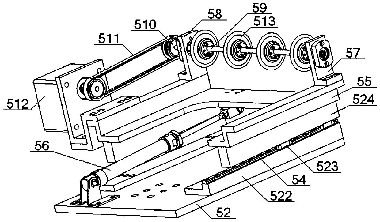
[0059] see figure 1 , figure 2 , image 3 , Figure 5 , the No. 1 guide rail 51 is fixed on the No. 1 height adjustment block 521, and a lifting device is arranged between the No. 1 height adjustment block 521 and the installation base plate 5; the spinning tube 4 is a circular platform structure, and the No. 2 guide rail 54 Be fixed on the cutting platform 52 by the taper adjustment block 522, the taper adjustment block 522 is a right angle trapezoidal structure, the oblique waist of the taper adjustment block 522 is connected with the No. 2 guide rail 54, and the right angle waist of the taper adjustment block 522 is in phase with the cutting platform Connect; slide block 523 is slidably connected on the No. 2 guide rail 54, and slide block 523 is connected with No. 2 height adjustment block 524 by elevating device, and No. 2 height adjustment block 524 is connected with motion base plate 55.
PUM
 Abstract
Description
Claims
Application Information
 - R&D
- Intellectual Property
- Life Sciences
- Materials
- Tech Scout
- Unparalleled Data Quality
- Higher Quality Content
- 60% Fewer Hallucinations
Browse by: Latest US Patents, China's latest patents, Technical Efficacy Thesaurus, Application Domain, Technology Topic, Popular Technical Reports.
© 2025 PatSnap. All rights reserved.Legal|Privacy policy|Modern Slavery Act Transparency Statement|Sitemap|About US| Contact US: help@patsnap.com