
Non-abrasion fiber cutting equipment

A fiber cutting equipment, non-abrasive technology, applied in fiber cutting, fiber processing, textiles and papermaking, etc., can solve the problems of yarn cutting blade damage, unusability, increased labor costs and financial costs, etc., to improve yarn cutting efficiency , prolong service life and save labor cost

Inactive Publication Date: 2015-04-29
秦皇岛洛克维德新材料技术有限公司
View PDF6 Cites 4 Cited by
  • Summary
  • Abstract
  • Description
  • Claims
  • Application Information

AI Technical Summary

Problems solved by technology

[0004] However, due to the extrusion structure of the yarn cutter roller and the pressure roller, the yarn cutting blade on the yarn cutter roller protrudes from the surface of the yarn cutter roller, and a certain pressure will act on the pressure roller when cutting the yarn. The surface of the bearing roller will be cut by the yarn cutting blade on the cutter roller, so after a large amount of yarn is cut or after a period of tight use, the surface of the bearing roller will be cut by the yarn cutter roller. The yarn process is severely damaged, so that it cannot be used, and the yarn cutting blade on the yarn cutter roller will also be damaged, and eventually the yarn cutting and throwing system cannot perform yarn cutting work, and the cutting blade on the yarn cutter roller can only be replaced and repaired. Yarn blades and pressure rollers increase labor costs and financial costs, and waste time

Method used


Image

  • Non-abrasion fiber cutting equipment
  • Non-abrasion fiber cutting equipment
  • Non-abrasion fiber cutting equipment

Examples


Embodiment Construction

[0021] Exemplary embodiments of the present invention will be described in detail below with reference to the accompanying drawings. These exemplary embodiments are provided so that those of ordinary skill in the art can clearly understand the present invention and implement the present invention from the description herein. The drawings and specific examples are not intended to limit the invention, the scope of which is defined by the appended claims.

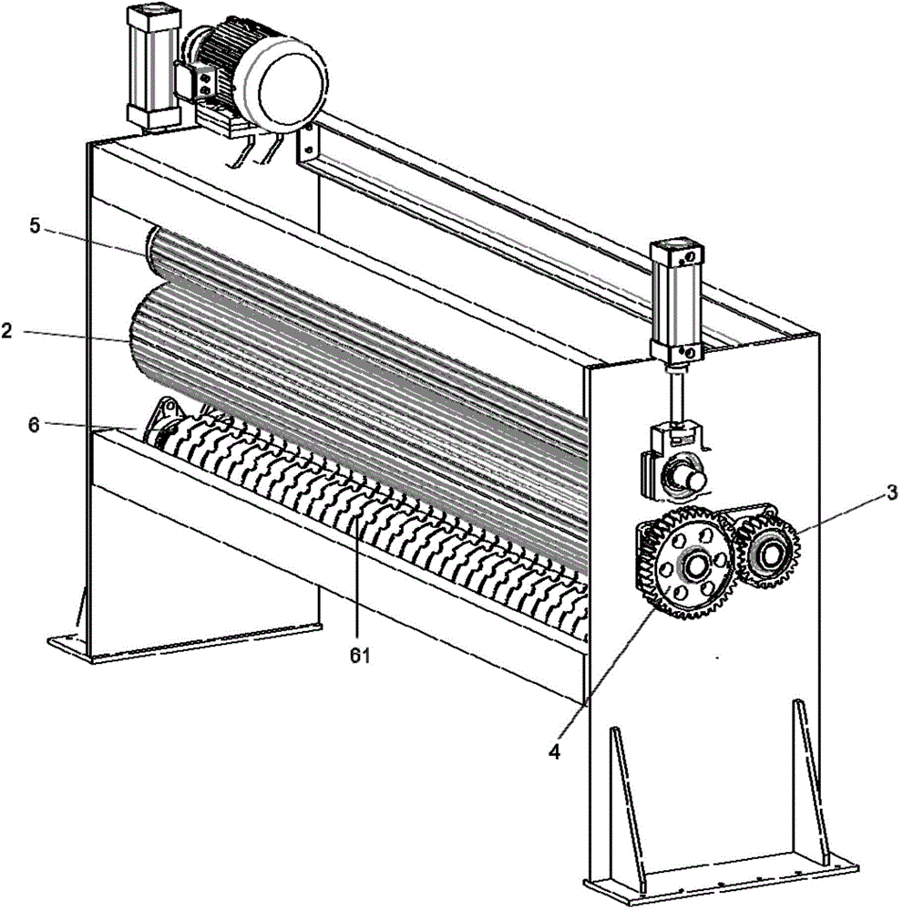
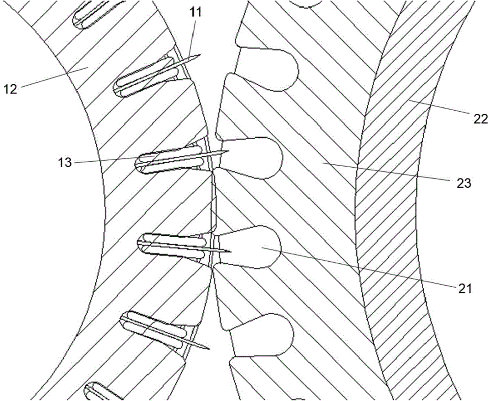
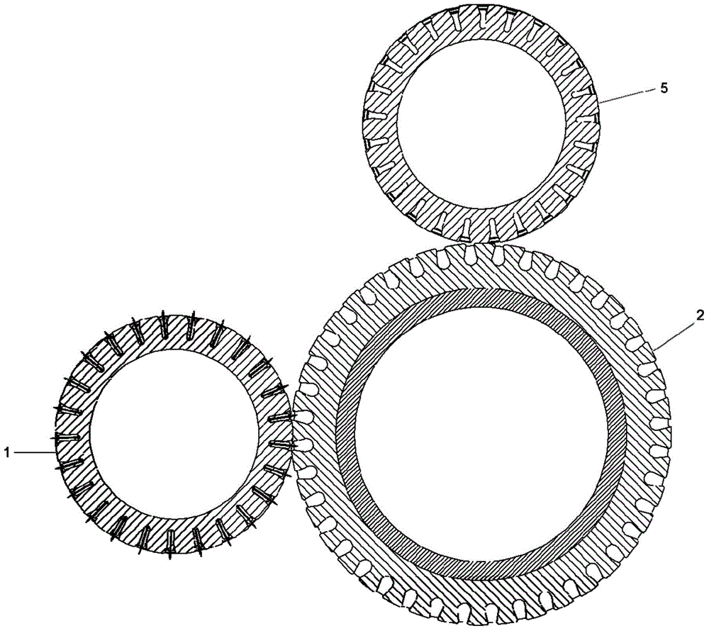
[0022] figure 1 A schematic diagram of the three-dimensional structure of the non-abrasive fiber cutting equipment provided by the embodiment of the present invention is shown; figure 2 show figure 1 A partially enlarged view of part of the structure of the non-abrasive fiber cutting equipment shown; image 3 show figure 1 Positional diagram of parts of the wear-free fiber cutting machine shown. refer to Figure 1 to Figure 3 The non-abrasive fiber cutting equipment provided by the present invention comprises a yarn cut...


PUM


Abstract

The invention provides non-abrasion fiber cutting equipment, which comprises a yarn cutting knife roll and a pressure roll, wherein the pressure roll is arranged near the side surface of the yarn cutting knife roll, a plurality of yarn cutting knife blades are uniformly arranged at the circumference surface of the yarn cutting knife roll, a plurality of hollow yarn cutting knife grooves are uniformly formed in the circumference surface of the pressure roll, the yarn cutting knife roll comprises a knife holder roll, the knife holder roll is of an axial hollow structure and is provided with a first hollow cavity, a plurality of grooves are uniformly formed in the circumference surface of the outer circle of the knife holder roll, a knife clip is arranged in each groove, each yarn cutting knife blade is clamped between the corresponding knife clips, and the position of each yarn cutting knife blade corresponds to the corresponding yarn cutting groove. The non-abrasion fiber cutting equipment has the advantage that as the position of each yarn cutting knife blade corresponds to the corresponding yarn cutting groove, and each yarn cutting knife blade is not in direct contact with the outer surface of the pressure roll, the service lives of each yarn cutting knife blade and the pressure roll are prolonged, the yarn cutting effect is better, and the yarn cutting efficiency is higher.

Description

technical field [0001] The invention relates to the field of glass fiber manufacturing equipment, in particular to a non-abrasive fiber cutting equipment. Background technique [0002] The automatic continuous molding production line of glass fiber products is composed of feeding system, scraping system, yarn cutting and throwing system, smoothing system, curing system, dust-free cutting system and dust-absorbing dividing system. The cutting and throwing system has Yarn cutting device for cutting yarn. [0003] The yarn cutter roller and the flat pressure roller of the yarn cutting device in the prior art are bonded and have a certain pressure, and the yarn cutting blade on the yarn cutter roller cuts the yarn between the yarn cutter roller and the pressure roller. Cutting and guiding, throwing down, this structure plays the role of cutting yarn, guiding yarn delivery, and throwing down. [0004] However, due to the extrusion structure of the yarn cutter roller and the pre...

Claims


Application Information

Patent Timeline
Patent Type & Authority Applications(China)
IPC IPC(8): D01G1/00
CPCD01G1/00
Inventor 裴晓松
Owner 秦皇岛洛克维德新材料技术有限公司
Learn More