Semi-underground multiple-row lifting and transferring cubic garage

A technology of lifting and moving, three-dimensional garage, which is applied in the direction of buildings, building types, and buildings where cars are parked. It can solve the problems of maximizing the area utilization rate, increase stability and use safety, and avoid direct force Effect

Active Publication Date: 2016-03-16
GUANGDONG SAMPU GARAGE CO LTD
View PDF7 Cites 2 Cited by
  • Summary
  • Abstract
  • Description
  • Claims
  • Application Information

AI Technical Summary

Problems solved by technology

However, this form still fails to maximize the utilization of the original area

Method used


Image

  • Semi-underground multiple-row lifting and transferring cubic garage
  • Semi-underground multiple-row lifting and transferring cubic garage
  • Semi-underground multiple-row lifting and transferring cubic garage

Examples


Embodiment 1

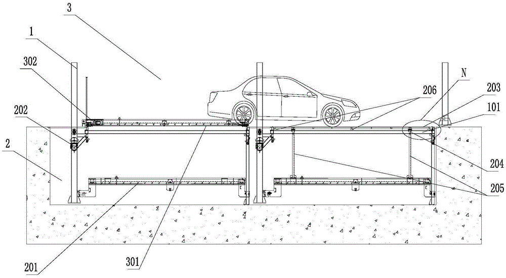
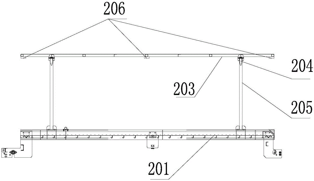
[0027] see figure 1 , a semi-underground multi-column lift-and-transfer three-dimensional garage, including a main frame 1 spliced ​​by a plurality of support beams and columns, the main frame 1 is a multi-row multi-row berth including a pit layer 2 and a ground layer 3, Among them, the third berth on the ground floor is provided with a traversing vehicle-carrying plate 301 and a first traversing drive mechanism 302 for controlling the lateral movement of the traversing vehicle-carrying plate 301; The pit lifting drive mechanism 202 used to control the up and down lifting of the pit vehicle-carrying plate 201; the pit patch 203 is respectively provided on the support beams of the first row of berths on the pit floor 2, so that the rear row of vehicles can pass through the front row of pits. Access the car.

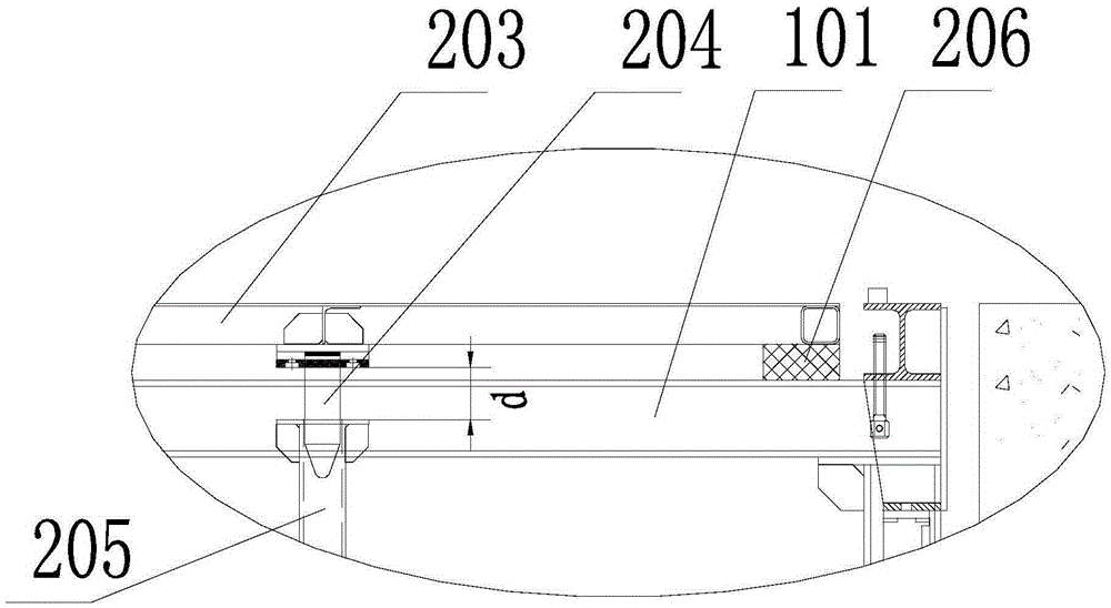
[0028] see Figures 2 to 4 , the pit patch 203 is arranged on the support beam 101 of the main frame 1, the pit patch 203 is provided with a connecting guide 204, and th...

Embodiment 2

[0035] see Figure 5 The difference between this embodiment and Embodiment 1 is that a second floor is also provided above the ground layer 3, and the berth on the second floor is provided with a lifting vehicle loading plate 400 and is used to control the lifting vehicle loading plate 400 to lift up and down. The lifting drive mechanism 500.

Embodiment 3

[0037] see Figure 6 The difference between this embodiment and Embodiment 1 is that several layers are arranged above the ground layer 3, including an intermediate layer 4 and a top layer 5, and the intermediate layer 4 berths are provided with a traversing trolley frame 401 placed on the traversing trolley. The first lifting vehicle loading plate 402 in the frame 401, the first lifting driving mechanism 403 and the second lateral movement driving mechanism 404, the first lifting driving mechanism 403 is used to control the first lifting vehicle loading plate 402 to lift up and down, and the second lateral movement The driving mechanism 404 is used to control the lateral movement of the trolley frame 401; the top floor 5 berth is provided with a second lifting vehicle loading plate 501 and a second lifting driving mechanism 502 for controlling the second lifting vehicle loading plate 501 to lift up and down.

[0038] The intermediate layer 4 consists of several layers. There...


PUM


Abstract

The invention provides a semi-underground multiple-row lifting and transferring cubic garage, comprising a main frame spliced by a plurality of support beams and stand columns. The main frame is multi-row multi-column parking stalls including a pit layer and a ground layer. The ground layer parking stall is provided with a transverse vehicle carrying board and a first transverse driving mechanism used to control the transverse vehicle carrying board to move transversely. The pit layer parking stall is provided with a pit vehicle carrying board and a pit lifting driving mechanism used to control the pit vehicle carrying board to lift up and down. The first row parking stall support beam of the pit layer is provided with a pit additional plate, so that a vehicle on the rear row can access through the front row pit. Through using the front-row pit additional plate structure, vehicle can access without barrier from the rear row through the front row pit. Under the condition that area is not changed, the number of parking stalls is maximized.

Description

technical field [0001] The invention relates to the technical field of three-dimensional garages, in particular to a semi-underground multi-row lift-and-slide three-dimensional garage. Background technique [0002] At present, due to the rapid increase in the growth rate of automobiles and the saturation of urban parking capacity, the so-called land is expensive, and parking difficulties have become an increasingly serious problem. Factors such as site restrictions and height restrictions have restricted the number of parking lots. To solve this Difficulties, different types of garages have emerged on the market. Among them, the multi-row lifting and traversing three-dimensional garage on the ground is the most common. It stores vehicles by stacking up and down above the ground and placing them front and back, effectively increasing the number of storage and retrieval vehicles on the basis of the original area. However, since the equipment is installed in an outdoor environ...

Claims


Application Information

Patent Timeline
IPC IPC(8): E04H6/22
CPCE04H6/22
Inventor 苏农陈文辉黎嘉殷
Owner GUANGDONG SAMPU GARAGE CO LTD
Why Eureka
Try Eureka