
Silent cloth finishing machine

A finishing machine and padding technology, which is applied in the direction of thin material processing, winding strips, sending objects, etc., can solve the problems of large size of tension sensor, easy damage of tension sensor, unstable output signal, etc., and improve the performance of speed regulation And energy-saving effect, eliminate physical wear and tear, prolong the effect of service life

Inactive Publication Date: 2010-06-23
SHANGHAI DIANJI UNIV +2
View PDF4 Cites 2 Cited by
  • Summary
  • Abstract
  • Description
  • Claims
  • Application Information

AI Technical Summary

Problems solved by technology

[0003] The disadvantage of the cloth finishing machine in the prior art is that, using the traditional tension detection technology, there are many moving parts and the volume of the tension sensor is large, especially the tension sensor and the transmission chain move together, which not only increases the instability of the detection system, but also makes the The tension sensor is easy to be damaged: this kind of device mostly uses an angle sensor, and most of them use an infinite potentiometer to detect the angle change of the tension sampling rod, and then detect the tension of the product to be tested, such as a pad
Since the core component of this sensor is the limitless potentiometer, and this component is connected by a chain and a tension sampling rod, the external impact force is often transmitted to this potentiometer due to various reasons on site. Damage; at the same time, since the potentiometer is connected to the tension sampling rod through a chain, the potentiometer moves left and right with the tension sampling rod at any time when the machine is working, which increases the physical wear of the potentiometer and makes its output signal unstable; The speed regulation performance of the traditional slip speed regulation system is not good, and the power factor is very low, which cannot achieve the energy saving effect; although the traditional DC speed regulation system has good speed regulation performance, it is expensive and troublesome in operation and maintenance
The traditional two-position photoelectric edge detection causes the edge detection follow-up mechanism to move from left to right, and the operation is extremely unstable, which leads to uneven rolling and forming of pad cloth or gray cloth

Method used

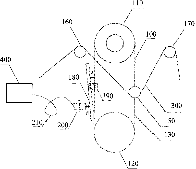

Image

  • Silent cloth finishing machine
  • Silent cloth finishing machine
  • Silent cloth finishing machine

Examples


Embodiment Construction

[0009] The present invention will be further described below in conjunction with the embodiments and with reference to the accompanying drawings.

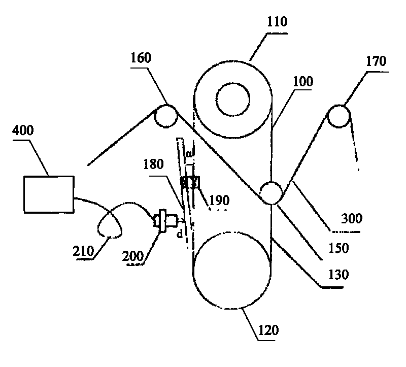
[0010] Such as figure 1 Shown is a schematic structural view of the cloth finishing machine of the present invention, a kind of cloth finishing machine, including a tension detection device 100, a speed regulating device 400 and a photoelectric edge detection device (not shown), the tension detection device 100 includes a first The loop formed by sprocket 110, second sprocket 120 and transmission chain 130, the first sprocket 110 and the second sprocket 120 are vertically arranged up and down, and the right side of transmission chain 130 is provided with a tension sampling roller 150, tension sampling The left and right sides of the roller 150 are respectively provided with two cloth guide rollers 160, 170 higher than the tension sampling roller 150, and the left side of the transmission chain 130 is provided with a metal strip 180...


PUM


Abstract

The invention discloses a silent cloth finishing machine, comprising a tensile force detection device, a speed regulation device and photoelectricity delineation device; the tensile force detection device comprises a loop composed of a first chain wheel, a second chain wheel and a transmission chain; one side of the transmission chain is provided with a tensile force sampling roller which is arranged between two cloth guide rollers, the other side of the transmission chain is provided with a metallic stick and a linear proximity switch; one fixed block of the metallic stick and the transmission chain form an included angle. The silent cloth finishing machine features stable operation and quick response speed.

Description

【Technical field】 [0001] The invention relates to the technical field of mechanical manufacturing, in particular to a pad finishing machine used by tire factories. 【Background technique】 [0002] Pad finishing machine is one of the commonly used equipment in tire factories. These equipment generally use traditional technical means. For example, the tension detection is through the weight tension frame structure, and the tension sampling rod and tension sensor (usually using angle sensor) connected; the speed regulation adopts the slip motor speed regulation or the DC motor speed regulation; the edge detection adopts the photoelectric two-position switch to detect the edge. [0003] The disadvantage of the cloth finishing machine in the prior art is that, using the traditional tension detection technology, there are many moving parts and the volume of the tension sensor is large, especially the tension sensor and the transmission chain move together, which not only increases ...

Claims


Application Information

Patent Timeline
Patent Type & Authority Applications(China)
IPC IPC(8): B65H23/26B65H23/00B65H43/00
Inventor 蒋新根宋国辉赵良范辉韩强
Owner SHANGHAI DIANJI UNIV
Learn More