

Plastic steel door and window corner welding reinforcement member and use method of same
A technology for plastic steel doors and windows and reinforcements, applied in welding equipment, welding equipment, auxiliary welding equipment, etc., can solve the problems of moldy wood blocks, heavy maintenance work, low plastic strength, etc., to prolong service life and reduce maintenance and repair. , The effect of reducing labor and cost
- Summary
- Abstract
- Description
- Claims
- Application Information
AI Technical Summary
Problems solved by technology
Method used
Image

Examples
Embodiment Construction
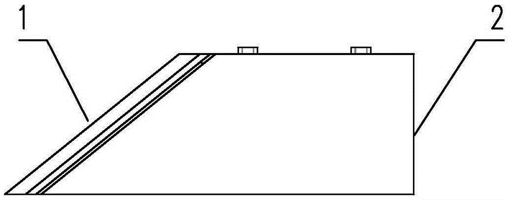
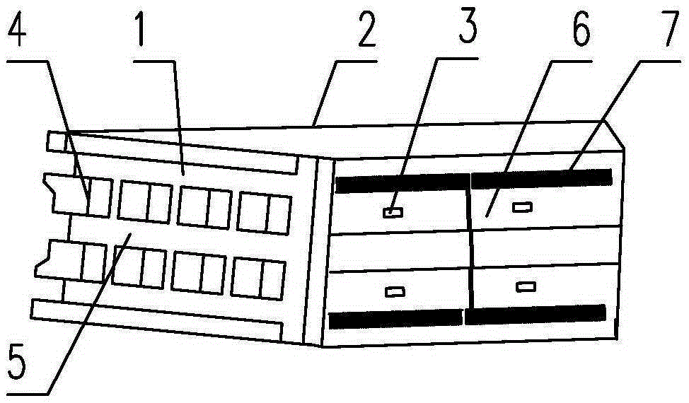
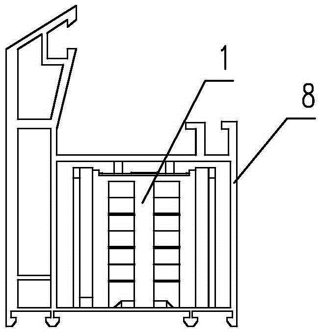
[0022] The present invention is specifically described below in conjunction with the accompanying drawings: Embodiment: Referring to the accompanying drawings, a corner welding reinforcement for plastic-steel doors and windows is provided with a reinforced corner piece 1 and a reinforced corner piece 2 with the same structure, both of which are at an angle of 45° at one end The square cylinder 2 of the slope 1, the 45° angle slopes of the two reinforced corner pieces are combined to form an L-shaped right angle shape; its shape and size match the middle cavity of the plastic steel door and window frame profile 8; the 45° angle There are raised blocks 4 and concave melting tanks 5 on the inclined surface, the shape and spacing of the raised blocks and the concave melting tanks are set as follows: when the two slopes are welded together, the raised blocks are melted and the concave melting tanks are formed A welding plane consistent with the length and width of the inclined plane...
PUM
 Abstract
Description
Claims
Application Information