
A Steady State Imaging Technology and Azimuth Recognition System for Surrounding Rock Cracks

An identification system, steady state technology, applied in earthwork drilling, wellbore/well components, construction, etc., can solve problems such as the development of borehole fissures, fragmentation degree, unfavorable analysis, probe positioning, etc. that cannot be clearly reflected, and achieve convenient Image processing and analysis, facilitating the acquisition of images, ensuring the effect of real reliability

Inactive Publication Date: 2019-04-05
XIAN UNIV OF SCI & TECH
View PDF10 Cites 0 Cited by
  • Summary
  • Abstract
  • Description
  • Claims
  • Application Information

AI Technical Summary

Problems solved by technology

[0003] Existing borehole peeping equipment generally includes three parts: host, probe and cable. It is easy to compare the price of borehole peeping in the vertical downward direction, but when the borehole deviates from the vertical direction at a certain angle or even when the borehole is vertically upward, the drill Hole peeking device is more difficult to use
At present, for oblique or vertical upward drilling peep image sampling, on-site gun sticks are generally used to bundle and transport peep probes. Because the probe cannot be positioned accurately, the imaging is not good, and during the process of transporting the probe, the swing of the gun stick and the probe will affect the hole. The wall causes damage, which is not conducive to the laboratory analysis of the image after imaging. Its shortcomings and shortcomings are as follows:
[0004] 1. The peeping probe cannot be fixed in the center of the borehole, resulting in blurred images of the borehole, which cannot clearly reflect important information such as the development of cracks in the borehole and the degree of fragmentation;
[0005] 2. During the transportation process in the peeping probe hole, due to human or equipment factors, it is easy to collide with the wall of the borehole, causing damage to the wall of the borehole, resulting in the acquired image not being able to truly reflect the situation on the spot, and causing misleading analysis of the later laboratory image;
[0006] 3. On-site peeping probe transportation is usually bundled with gun sticks, connected by multiple sections, and the quality is large, which causes great difficulties for the in-hole transportation of peeping probes drilled in medium-deep holes or deep holes;
[0007] 4. There is a lack of azimuth reference objects. During the analysis process of the borehole peep image laboratory, the azimuth of the target area cannot be distinguished from the image, which makes it difficult for target positioning

Method used


Image

  • A Steady State Imaging Technology and Azimuth Recognition System for Surrounding Rock Cracks
  • A Steady State Imaging Technology and Azimuth Recognition System for Surrounding Rock Cracks
  • A Steady State Imaging Technology and Azimuth Recognition System for Surrounding Rock Cracks

Examples


Embodiment Construction

[0025] The technical solution of this patent will be further described in detail below in conjunction with specific embodiments.

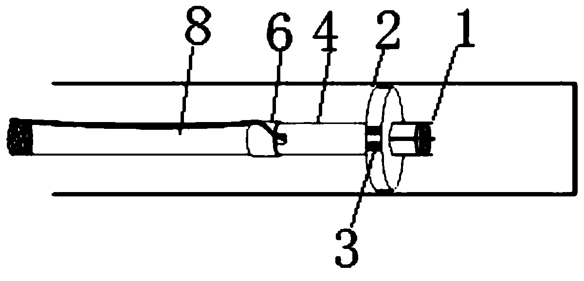
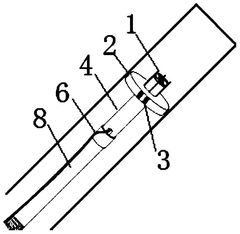
[0026] A steady-state imaging technology for cracks in surrounding rocks and an azimuth recognition system, including an azimuth indicating column 1, a fixed disk 2 in a steady-state imaging hole, a sliding roller 3 on the hole wall, a fixed probe tube 4, a cable outlet 5, and a connector 6 , compass 7, and probe conveying tube 8, the lower part of the probe fixing tube 4 is provided with a cable outlet 5, the upper part of the probe fixing tube 4 is connected to the fixed disc 2 in the steady-state imaging hole, and the fixed disc 2 in the steady-state imaging hole is used For the fixed probe, several hole wall sliding rollers 3 are provided on the outer surface of the fixed disk 2 in the steady-state imaging hole. The hole wall sliding rollers 3 of the present invention are provided with two, and the hole wall sliding rollers 3 are made of rubber ...


PUM


Abstract

The invention discloses surrounding rock fracture steady-state imaging technology and an orientation identification system. The surrounding rock fracture steady-state imaging technology involves orientation indication columns, a steady-state imaging hole inside fixing disc, hole wall sliding rolling wheels, a circular probe fixing pipe, a cable outlet, a connection head, a compass and a circular probe delivery pipe. The cable outlet is formed in the lower portion of the circular probe fixing pipe. The steady-state imaging hole inside fixing disc is connected to the upper portion of the circular probe fixing pipe. The multiple hole wall sliding rolling wheels are arranged on the outer side face of the steady-state imaging hole inside fixing disc. The multiple orientation indication columns are arranged in the middle of the steady-state imaging hole inside fixing disc. The circular probe delivery pipe is connected with the lower portion of the circular probe fixing pipe. Compared with the prior art, center fixing and steady-state imaging of drilling peeping probes can be achieved, labor is saved and the probes are delivered without damage through the hole wall sliding rolling wheels, intra-hole orientation indication is achieved, the mass is light, strength is high, and carrying is convenient.

Description

technical field [0001] The invention relates to the technical field of surrounding rock fissure detection, in particular to a surrounding rock fissure steady-state imaging technology and an orientation recognition system. Background technique [0002] The optical imaging of surrounding rock fractures based on drilling is a research method that continuously samples the surrounding rock fractures through on-site drilling, and then evaluates and analyzes the images in the later stage to grasp the geological conditions of the site. It is widely used in mines, engineering geology, hydrogeology, rock civil engineering and other departments. When performing image sampling, the peep probe should be fixed in the center of the borehole and the equipment should not be violently hit the hole wall to achieve clear and non-destructive imaging of the hole wall. [0003] Existing borehole peeping equipment generally includes three parts: host, probe and cable. It is easy to compare the pri...

Claims


Application Information

Patent Timeline
Patent Type & Authority Patents(China)
IPC IPC(8): E21B49/00E21B47/002E21B47/017
Inventor 来兴平杨毅然崔峰单鹏飞曹建涛孙欢葛睿智张磊刘辉刘简宁
Owner XIAN UNIV OF SCI & TECH
Learn More