A fan damping shaft

A shock absorber shaft and fan technology, applied in liquid fuel engines, machines/engines, mechanical equipment, etc., can solve the problems of shock absorber rubber prolapse damage, inability to locate axially, poor vibration damping effect, etc., to reduce vibration amplitude , to avoid rigid contact, the effect of reasonable mass distribution

Active Publication Date: 2018-09-25
GUANGXI YUCHAI MASCH CO LTD
View PDF3 Cites 0 Cited by
  • Summary
  • Abstract
  • Description
  • Claims
  • Application Information

AI Technical Summary

Problems solved by technology

The existing scheme has poor vibration damping effect, difficult disassembly and assembly, and cannot be positioned axially, and the rubber of the shock absorber often breaks out and is damaged.

Method used


Image

  • A fan damping shaft
  • A fan damping shaft
  • A fan damping shaft

Examples


Embodiment 1

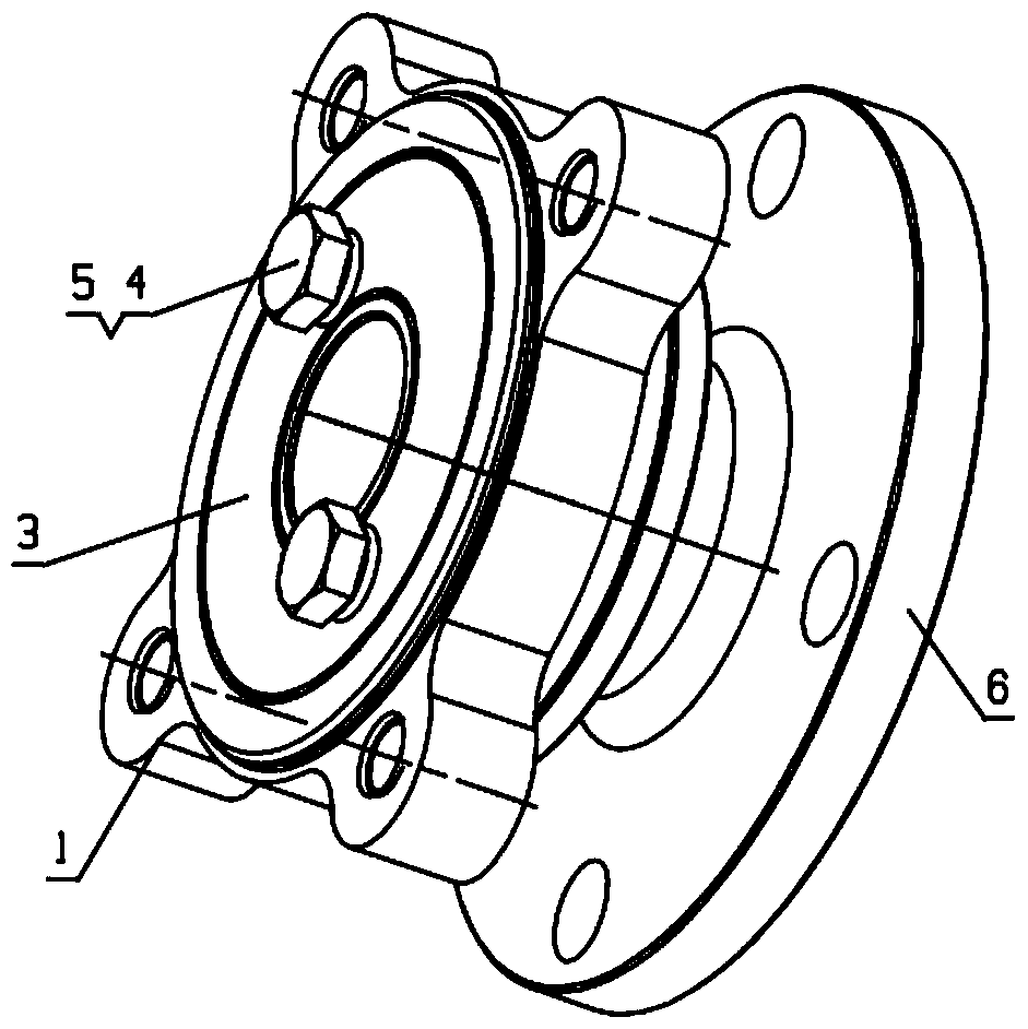
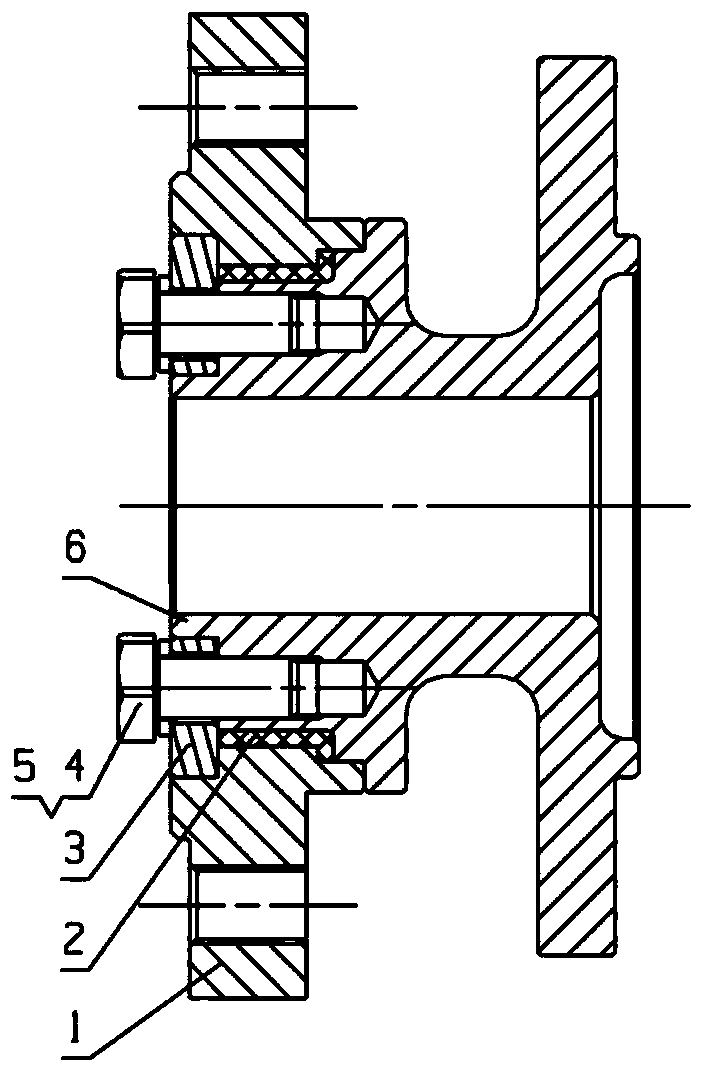
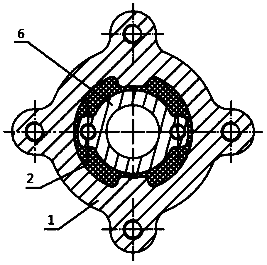
[0031] The specific embodiment of the present invention is as Figure 1 to Figure 6 As shown, it is a fan damping shaft, including a first flange 1 and a second flange 6; the first flange 1 and the second flange 6 are connected by a shaft hole, and there is also a preventive The rubber ring 2 that is rigidly connected between the two is provided with concave-convex matching structures between the first flange 1 and the rubber ring 2, and between the second flange 6 and the rubber ring 2. structure.

[0032] The first flange 1 is provided with a mounting hole, the second flange 6 is provided with a mounting shaft, and the rubber ring 2 is arranged between the mounting hole and the mounting shaft, wherein the rubber ring 2 acts as a shock absorber, which can effectively reduce the engine crankshaft The damage degree of the instantaneous torsional vibration inertia force to the mounting bolts and other parts.

[0033] A shaft shoulder 12 is arranged on the outer end surface of ...


PUM


Abstract

The invention discloses a fan shock absorption shaft which comprises a first flange and a second flange. The first flange and the second flange are connected through a shaft hole. A rubber ring for preventing the first flange and the second flange from being connected in a rigid manner is arranged between the first flange and the second flange. Concave-convex matching structures are arranged between the first flange and the rubber ring and between the second flange and the rubber ring respectively. The rubber ring is provided with a structure for preventing the rubber ring from being separated in the axial direction. The fan shock absorption shaft is simple in structure, convenient to mount, good in shock absorption effect, capable of transmitting larger torque and free of generating rubber separation or even damage.

Description

technical field [0001] The invention relates to the field of engine cooling, in particular to a fan damping shaft. Background technique [0002] The fan transmission shaft is installed and fixed between the front end of the engine and the fan, so that the fan rotates with the crankshaft of the engine, so that the fan cools the engine. In order to reduce the damage degree of the instantaneous torsional vibration inertial force of the engine crankshaft to the mounting bolts and other parts, it is necessary to add a rubber ring with a vibration damping function on the fan shaft. At present, there are two main fan shaft structures used for vibration reduction. One is that the vibration damping rubber adopts the same thin rubber ring as the belt pulley damper structure, and the other uses screws to fix the outer ring flange and the vibration damping rubber. The damping rubber has bosses, and the inner ring flange has concave holes, and the vibration damping rubber and the inner ...

Claims


Application Information

Patent Timeline
Patent Type & Authority Patents(China)
IPC IPC(8): F04D29/053F04D29/054F04D29/66F01P5/02
CPCF01P5/02F04D29/053F04D29/054F04D29/661
Inventor 李少明胡国强陈剑涛赵增亮
Owner GUANGXI YUCHAI MASCH CO LTD
Why Eureka
Try Eureka