Oil cylinder tail end automatic lockup valve and hydraulic oil cylinder with oil cylinder tail end automatic lockup valve

An automatic locking and hydraulic cylinder technology, applied in the field of hydraulic cylinders, can solve problems such as poor locking, leakage, and slow movement of hydraulic cylinder piston rods

Inactive Publication Date: 2016-03-16
ZHENGZHOU YUTONG HEAVY IND
View PDF7 Cites 10 Cited by
  • Summary
  • Abstract
  • Description
  • Claims
  • Application Information

AI Technical Summary

Problems solved by technology

[0004] Although the existing technical means have realized the locking function of the piston rod of the hydraulic cylinder to a certain extent, in some cases, due to the degree of oil pollution in the hydraulic system, the hydraulic lock or the balance valve will be stuck, leaked, or due to the existence of the hydraulic cylinder. The reasons for the allowable internal leakage will lead to the poor sealing of the large and small chambers of the hydraulic cylinder when the main engine is not working, which will cause the piston rod of the hydraulic cylinder to move slowly and the locking is not firm. In severe cases, it will cause safety problems

Method used


Image

  • Oil cylinder tail end automatic lockup valve and hydraulic oil cylinder with oil cylinder tail end automatic lockup valve
  • Oil cylinder tail end automatic lockup valve and hydraulic oil cylinder with oil cylinder tail end automatic lockup valve
  • Oil cylinder tail end automatic lockup valve and hydraulic oil cylinder with oil cylinder tail end automatic lockup valve

Examples


Embodiment Construction

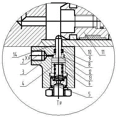
[0020] as shown in the picture image 3 As shown, an automatic locking valve at the end of an oil cylinder includes a valve body 3 installed on the wall of the oil cylinder at the end of the oil cylinder. The valve body is provided with a valve core 7 extending into the oil cylinder. The core plate is installed on the mandrel, and the lower part of the valve core is provided with a spring chamber 6, and the core plate and the spring chamber are connected by a friction pair, and the return spring 4 is set on the mandrel at the lower part of the core plate, and the core plate The length of the lower mandrel is less than the height of the spring cavity at the lower part of the core plate. The bottom of the spring cavity is provided with an oil drain plug 5, and the oil drain plug is threadedly connected with the valve body; a sealing ring 9 is arranged between the valve core and the valve body, and the valve body and the valve core at the bottom of the sealing ring are enclosed ...


PUM


Abstract

The invention discloses an oil cylinder tail end automatic lockup valve and a hydraulic oil cylinder with the oil cylinder tail end automatic lockup valve. The automatic lockup valve comprises a valve body mounted on the oil cylinder wall at the tail end of an oil cylinder, wherein a valve element stretching into the oil cylinder is arranged on the valve body; a spring cavity is formed below the valve element; reset springs are arranged in the spring cavity; an oil leakage plug is arranged at the bottom of the spring cavity; a seal ring is arranged between the valve element and the valve body; a cavity formed between the valve body below the seal ring and the valve element is a guide oil cavity; a guide oil port is formed in the side wall of the valve body; and the guide oil port is communicated with the guide oil cavity. An hydraulic oil cylinder piston rod is completely locked up and is prevented from accidently moving through a lockup structure of a novel oil cylinder.

Description

technical field [0001] The invention relates to a hydraulic oil cylinder with mechanical stroke positioning. Through the mechanical lock valve of the hydraulic oil cylinder, the piston rod of the hydraulic oil cylinder can be effectively positioned at the required working stroke position and ensure that when the main engine stops and does not work, the hydraulic pressure The piston rod stop position of the cylinder effectively remains unchanged. Background technique [0002] The hydraulic cylinder is a linear reciprocating hydraulic component. The piston rod inside the hydraulic cylinder does not have the function of locking at a specific position inside the cylinder of the hydraulic cylinder in the current technology. However, in the daily engineering application process, the hydraulic cylinder is often required. When the piston rod moves to a certain position, it is locked and no longer moves. [0003] In order to realize the locking function, in the current technology, a...

Claims


Application Information

Patent Timeline
Patent Type & Authority Applications(China)
IPC IPC(8): F15B15/26
Inventor 刘华亮薛占刚李楠王汉杰冯会娟王斌
Owner ZHENGZHOU YUTONG HEAVY IND
Why Eureka
Try Eureka