Detonating tube electronic delay detonator and method for detonating detonator under double control of light and shock waves

A technology of delayed detonators and detonators, applied in the direction of electric fuzes, weapon accessories, fuzes, etc., can solve the problems of national production safety impact, accidental explosion, personal and property losses, etc., to prevent accidental explosion, reduce the probability of accidental explosion, The effect of improving safety

Active Publication Date: 2016-03-16
XIANGNAN EXPLOSION APPLIANCES HUNAN PROV
View PDF9 Cites 4 Cited by
  • Summary
  • Abstract
  • Description
  • Claims
  • Application Information

AI Technical Summary

Problems solved by technology

For example: when there is a sudden change in the external temperature, the same non-electricity in the outside world is directly discharged on the sensitive element and converted into a switching electrical signal, and when there is a sudden strong shock wave vibration in the outside world, it may cause false explosion; during use and transportation, once encountered When a certain emergency occurs, the nonel electronic delay detonator will explode by mistake, which may have a great impact on national production safety, bring losses to people and property, and lead to irreparable consequences

Method used


Image

  • Detonating tube electronic delay detonator and method for detonating detonator under double control of light and shock waves
  • Detonating tube electronic delay detonator and method for detonating detonator under double control of light and shock waves
  • Detonating tube electronic delay detonator and method for detonating detonator under double control of light and shock waves

Examples


Embodiment 1

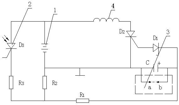
[0024] Such as figure 2 As shown, the AND gate electronic delay detonation circuit of this embodiment includes a battery power supply 1, a light control switch 2, a current limiting resistor R1, a resistor R2, a voltage dividing resistor R3, a shock wave delay switch 3, a capacitor C, a diode D1, a single To thyristor D2, bridge wire 4. The input terminal of the light control switch 2 is connected to the positive pole of the battery power supply 1, the input terminal of the voltage dividing resistor R3 is connected to the output terminal of the light control switch 2, and the output terminal is connected to the input terminals of the current limiting resistor R1 and the resistor R2, and the shock wave delay The input terminal of switch 3 and the positive pole of capacitor C are all connected to the output terminal of current limiting resistor R1, the output terminal of resistor R2, the output terminal of shock wave delay switch 3 and the negative pole of capacitor C are all c...

Embodiment 2

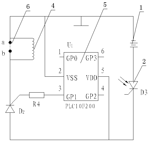
[0028] Such as image 3 As shown, the AND gate electronic delay detonation circuit of this embodiment includes a battery power source 1, a light control switch 2, a bridge wire 4, a fourth resistor R4, a shock wave bridge wire path switch 6, a single-chip microcomputer delay control module 5, and a one-way thyristor D2, the input end of the light control switch 2 is connected to the positive pole of the battery power supply 1, the single-chip delay control module 5 selects PLC10F200 control chip, the fifth pin VDD of the single-chip delay control module 5 is connected to the output end of the light control switch 2, the second The 2-pin VSS is connected to the negative pole of the battery power supply 1, the 3rd pin GP1 is connected to the fourth resistor R4, the fourth resistor R4 is connected to the control pole of the one-way thyristor D2, and the anode of the one-way thyristor D2 is connected to the light control switch 2 The output end is connected, the cathode is connect...


PUM


Abstract

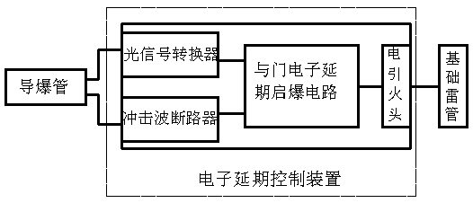
The invention relates to a detonating tube electronic delay detonator and a method for detonating the detonator under the double control of light and shock waves. The detonating tube electronic delay detonator comprises a detonating tube, a basic detonator body and an electronic delay control device. The electronic delay control device comprises an AND gate electronic delay detonation circuit, an electric firing head, a light signal converter and a shock wave circuit breaker, wherein the electric firing head is connected with the output end of the AND gate electronic delay detonation circuit, the light signal converter receives a light signal after the detonating tube is detonated to enable one control end of the AND gate electronic delay detonation circuit to be switched on, and the shock wave circuit breaker receives a shock wave signal after the detonating tube is detonated to enable the other control end of the AND gate electronic delay detonation circuit to be switched on. The electronic delay control device carries out the double control through the light and the shock waves, the light signal converter and the shock wave circuit breaker can trigger the AND gate electronic delay detonation circuit to start a delay procedure after simultaneously switching on the respectively controlled control ends, and after set time is up, the electric firing head emits fire to detonate the basic detonator body.

Description

technical field [0001] The invention relates to the technical field of detonation detonators, in particular to a nonel electronic delay detonator and a method for using light and shock wave dual control detonation nonel electronic delay detonators. Background technique [0002] With the development of blasting technology, electronic detonators have been used in conventional blasting systems, but due to the application and popularization of modern equipment, static electricity, electromagnetic waves, radio frequency stray currents, etc. have also increased relatively, which brings certain problems to the use of conventional electronic delay detonators harm. At present, most of the electronic detonators in my country use electronic leads to detonate the detonators after the detonator is energized. Tube detonators began to be developed and widely used. However, its disadvantage is that it is difficult to achieve high precision by means of chemical combustion delay, and the det...

Claims


Application Information

Patent Timeline
Patent Type & Authority Applications(China)
IPC IPC(8): F42C19/12F42C11/06
CPCF42C11/06F42C19/12
Inventor 张国荣张伟邓华
Owner XIANGNAN EXPLOSION APPLIANCES HUNAN PROV
Why Eureka
Try Eureka