Dam interior inertial navigation monitoring device automatic traction system
A monitoring device and traction system technology, which is applied in measurement devices, surveying and navigation, height/level measurement, etc., can solve the problems of rough traction mode, difficult positioning of monitoring vehicles, and difficult fixed-point measurement of key parts.
- Summary
- Abstract
- Description
- Claims
- Application Information
AI Technical Summary
Problems solved by technology
Method used
Image

Examples
Embodiment 1
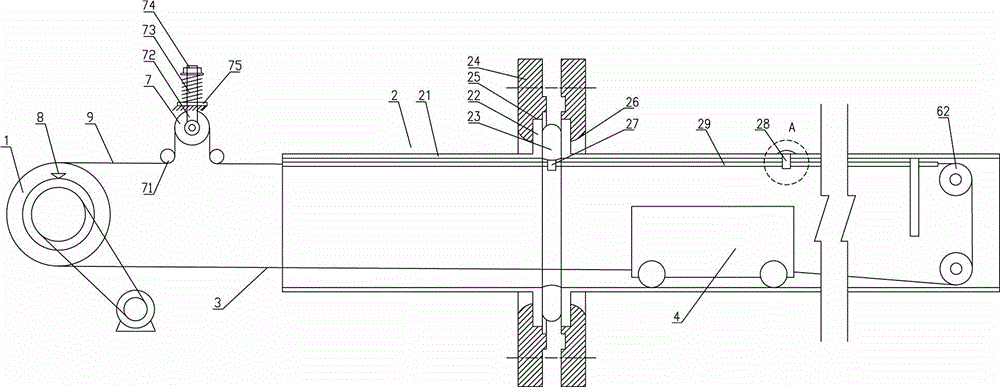
[0037] An automatic traction system for a dam internal inertial navigation monitoring device, comprising a traction device 6, a hoisting device driven by a driving device to rotate is arranged in the traction device 6, a traction rope 3 bypasses the hoisting device, and the traction rope 3 is connected with the hoisting device along the The monitoring device 4 that the flexible detection tube 2 travels is connected;
[0038] Also comprise rotatable first guide wheel 7, traction rope 3 walks around first guide wheel 7, is provided with wrapping angle guide wheel 71 at the front and back of first guide wheel 7, to increase traction rope 3 in the first guide The wrap angle on the wheel 7, in this example, the wrap angle of the traction rope 3 on the first guide wheel 7 is greater than 180 °, thus the structure prevents the traction rope 3 from slipping on the first guide wheel 7, ensuring that the traction rope 3 Keep synchronization between the movement of the first guide wheel ...
Embodiment 2
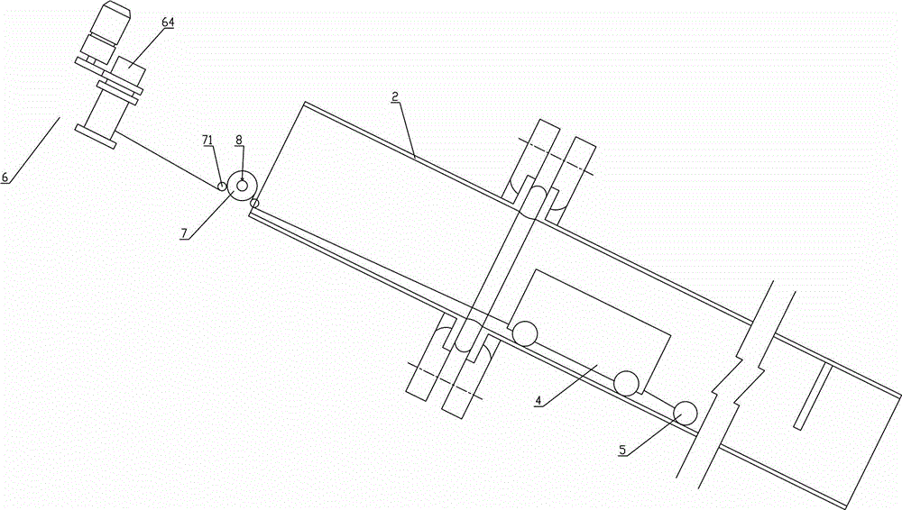
[0041] The preferred solution is as figure 1 Among them, on the basis of Embodiment 1, the flexible detection tube 2 is arranged obliquely, the hoisting device is a reel 61 driven to rotate by the driving device, and the traction rope 3 is connected to the tail of the monitoring device 4. The head of the monitoring device 4 is connected with a weight 5 . The specific structure of the hoisting device is as follows: the servo motor 63 is connected with the reel 61 through a reducer 65, and the reducer includes a worm gear reducer, a gear reducer and a belt reducer, and one or more combinations thereof can be selected. Preferably, a damper 64 is also provided on the shaft of the reel 61 or the reducer, and a magnetic powder damper is selected in this example. When in use, the monitoring device 4 slides down along the flexible detection tube 2 by the weight of the weight 5 of about 5 kg and the weight of the monitoring device 4 itself, the traction rope 3 drives the first guide w...
Embodiment 3
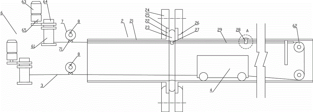
[0043] On the basis of Example 1, such as figure 2 Among them, the hoisting device is a reel 61 driven to rotate by a driving device. The specific structure of the hoisting device is: the servo motor 63 is connected to the reel 61 through a reducer 65, and the reducer includes a worm gear reducer, a gear reducer and One or more combinations of belt reducers can be selected. Preferably, a damper 64 is also provided on the shaft of the reel 61 or the reducer, and a magnetic powder damper is selected in this example.
[0044] There are two groups of hoisting devices, the traction rope 3 of one group of hoisting devices is connected to the tail of the monitoring device 4, and the traction rope 3 of the other group of hoisting devices bypasses the tube bottom guide wheel 62 at the bottom of the flexible detection tube 2 Connect with the head of the monitoring device 4. In a preferred solution, the first guide wheels 7 are correspondingly divided into two groups, so as to obtain mo...
PUM
 Abstract
Description
Claims
Application Information
 - R&D
- Intellectual Property
- Life Sciences
- Materials
- Tech Scout
- Unparalleled Data Quality
- Higher Quality Content
- 60% Fewer Hallucinations
Browse by: Latest US Patents, China's latest patents, Technical Efficacy Thesaurus, Application Domain, Technology Topic, Popular Technical Reports.
© 2025 PatSnap. All rights reserved.Legal|Privacy policy|Modern Slavery Act Transparency Statement|Sitemap|About US| Contact US: help@patsnap.com