Radar signal phase encoding law recognition method and device

A radar signal and phase encoding technology, applied in the field of electronic reconnaissance signal analysis, can solve the problem of high error rate of radar signal recognition and achieve high accuracy

Inactive Publication Date: 2018-11-06
PLA STRATEGIC SUPPORT FORCE INFORMATION ENG UNIV PLA SSF IEU
View PDF2 Cites 0 Cited by
  • Summary
  • Abstract
  • Description
  • Claims
  • Application Information

AI Technical Summary

Problems solved by technology

[0004] The purpose of the present invention is to provide a method and device for identifying radar signal phase encoding rules to solve the problem of high error rate in radar signal identification in the prior art

Method used


Image

  • Radar signal phase encoding law recognition method and device
  • Radar signal phase encoding law recognition method and device
  • Radar signal phase encoding law recognition method and device

Examples


Embodiment Construction

[0031] In order to make the object, technical solution and advantages of the present invention clearer, the present invention will be further described in detail below in conjunction with the accompanying drawings and embodiments.

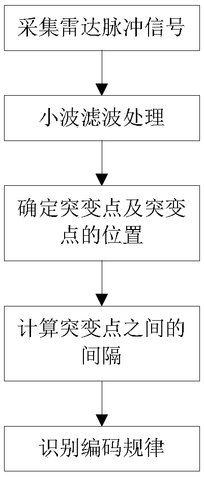
[0032] The present invention provides a radar signal phase encoding law identifying device, which includes a processor, and the processor is used to execute instructions to realize the radar signal phase encoding law identifying method of the present invention. Combine below figure 1 , to describe the method in detail.

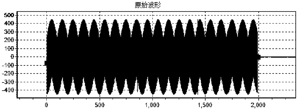
[0033] First, the radar pulse signal is collected. Suppose the received radar pulse signal is as figure 2 As shown, it is s(t):

[0034] s(t)=a(t)exp{j2πf 0 t}+w(t), 0≤t≤T

[0035] In the above formula, a(t) represents the baseband signal of the radar emitter signal, f 0 Represents the carrier frequency of the signal, w(t) represents the receiver noise signal, and T represents the duration of the pulse signal.

[0036] Supp...


PUM


Abstract

The invention relates to a radar signal phase encoding law recognition method and device. The method includes the following steps that: radar pulse signals are acquired; wavelet filtering processing is performed on the collected radar pulse signals, so that filtered radar pulse signals can be obtained; the abrupt change points of the filtered radar pulse signals and the corresponding positions ofthe abrupt change points are determined; and intervals between every two adjacent abrupt change points are calculated, and the intervals are sequentially recorded; and the encoding law of the radar signals is recognized according to the sequentially recorded intervals. The method of the invention has the advantages of simplicity, high reliability and high radar number recognition accuracy.

Description

technical field [0001] The invention belongs to the technical field of electronic reconnaissance signal analysis, and in particular relates to a method and a device for identifying phase encoding rules of radar signals. Background technique [0002] Precise processing of received radar emitter signals is an important content of electronic reconnaissance and an important means of information assurance. Among them, the accurate analysis and processing of the coding law of the radar signal emitter is an important part of it, and the accurate parameters of the radar emitter signal can be obtained, which is an important basis for radar signal identification and sorting processing, and is of great significance. [0003] The reliability of the traditional identification method of five characteristic parameters based on pulse descriptors has declined sharply, and it is difficult to meet the needs. With the continuous advancement of technology, new system radars emerge in an endless...

Claims


Application Information

Patent Timeline
Patent Type & Authority Applications(China)
IPC IPC(8): G01S13/02
CPCG01S13/02
Inventor 胡德秀黄洁赵拥军骆丽萍黄东华陈世文张睿张弛赵砚赵泽亚
Owner PLA STRATEGIC SUPPORT FORCE INFORMATION ENG UNIV PLA SSF IEU
Why Eureka
Try Eureka