Device and method for detecting and identifying glass defects
A glass defect and glass technology, which is applied in the field of detection of defects in glass, can solve the problems such as the inability to directly detect the Pt flash point in large-size glass, and achieve the effects of low manufacturing cost, reasonable structure and simple operation method
- Summary
- Abstract
- Description
- Claims
- Application Information
AI Technical Summary
Problems solved by technology
Method used
Image
Examples
Embodiment 1
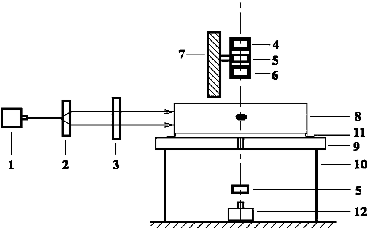
[0037] The device for detecting and identifying glass defects provided by this embodiment, such as figure 1 As shown, it includes a sample carrying unit, a defect detection unit and a defect discrimination unit, wherein the sample carrying unit includes a base 10, and a stage 9 arranged on the base 10, and the stage 9 can be moved up and down. Movement, used to adjust the height of the glass 8 to be detected, the light hole is provided on the stage 9, and the moving assembly 11 arranged on the stage 9, the moving assembly 11 is used to move the glass to be inspected The glass aligns the glass defect with the light hole; the defect detection unit includes a laser 1 that emits laser light and a beam expander 2 that expands the laser light. After the laser beam is expanded by the beam expander 2, it scans the glass to be detected 8. To determine the position of the glass defect, the defect detection unit also includes a shielding screen 3, which can be moved to block or not block...
Embodiment 2
[0040] This embodiment provides a method for detecting and identifying glass defects, which includes the following steps:
[0041](1) Polishing an ultra-short flint glass blank with a size of 300×300×40 mm.
[0042] (2) Start laser 1 and beam expander 2 (×10), said laser 1 is a commercially available 300mW single longitudinal mode green laser, wavelength 532nm, beam diameter 1.5mm; adjust stage 9, from the glass to be detected 8 Laser scanning is performed layer by layer from the bottom of the sample. If non-vitreous defects appear in the scanning area, the defect area is adjusted to the center position of the stage 9, and the laser scanning is suspended.
[0043] (3) Start the white light source 12, adjust the distance between the objective lens 4 and the glass 8 to be detected, and find non-vitreous defects in the field of view of the eyepiece 4 . Adjust the magnification (×100) of the eyepiece and objective lens to ensure that the defect image is clear. Adjust the polariz...
Embodiment 3
[0048] This embodiment provides a method for detecting and identifying glass defects, which includes the following steps:
[0049] (1) Polish the DM305 glass blank with a size of Φ400×30mm.
[0050] (2) start laser 1 and beam expander 2 (×5), described laser 1 is commercially available 200mW single longitudinal mode blue light laser, wavelength 457nm, beam diameter 1mm, open shielding screen 3, adjust stage 9, from Layer-by-layer laser scanning starts from the bottom of the glass sample. If there is a non-vitreous defect in the scanning area, adjust the defect area to the center of the stage 9, and use the shielding screen 3 to suspend the laser scanning.
[0051] (3) Start the white light source 12, adjust the distance between the objective lens 6 and the glass, and find non-vitreous defects in the field of view of the eyepiece 4. Adjust the magnification (×200) of the eyepiece and objective lens to ensure that the defect image is clear. Adjust the polarizer 5, if the defec...
PUM
| Property | Measurement | Unit |
|---|---|---|
| diameter | aaaaa | aaaaa |
| wavelength | aaaaa | aaaaa |
| diameter | aaaaa | aaaaa |
Abstract
Description
Claims
Application Information
 - R&D
- Intellectual Property
- Life Sciences
- Materials
- Tech Scout
- Unparalleled Data Quality
- Higher Quality Content
- 60% Fewer Hallucinations
Browse by: Latest US Patents, China's latest patents, Technical Efficacy Thesaurus, Application Domain, Technology Topic, Popular Technical Reports.
© 2025 PatSnap. All rights reserved.Legal|Privacy policy|Modern Slavery Act Transparency Statement|Sitemap|About US| Contact US: help@patsnap.com

