Photosensitive drum drive component and selenium drum including same

A photosensitive drum driving and photosensitive drum technology, which is applied in optics, electrical recording process using charge pattern, equipment using electrical recording process with charge pattern, etc. The problem of high rate, to achieve the effect of low failure rate and high stability

Pending Publication Date: 2016-03-16
新化凯尔影印科技有限公司
View PDF6 Cites 11 Cited by
  • Summary
  • Abstract
  • Description
  • Claims
  • Application Information

AI Technical Summary

Problems solved by technology

[0005] The above-mentioned structure and installation method of the drive assembly makes it easy for the drive force receiver 003 to come out of the gear structure 002, which in turn leads to a high failure rate and poor stability of the drive assembly

Method used


Image

  • Photosensitive drum drive component and selenium drum including same
  • Photosensitive drum drive component and selenium drum including same
  • Photosensitive drum drive component and selenium drum including same

Examples


Embodiment 1

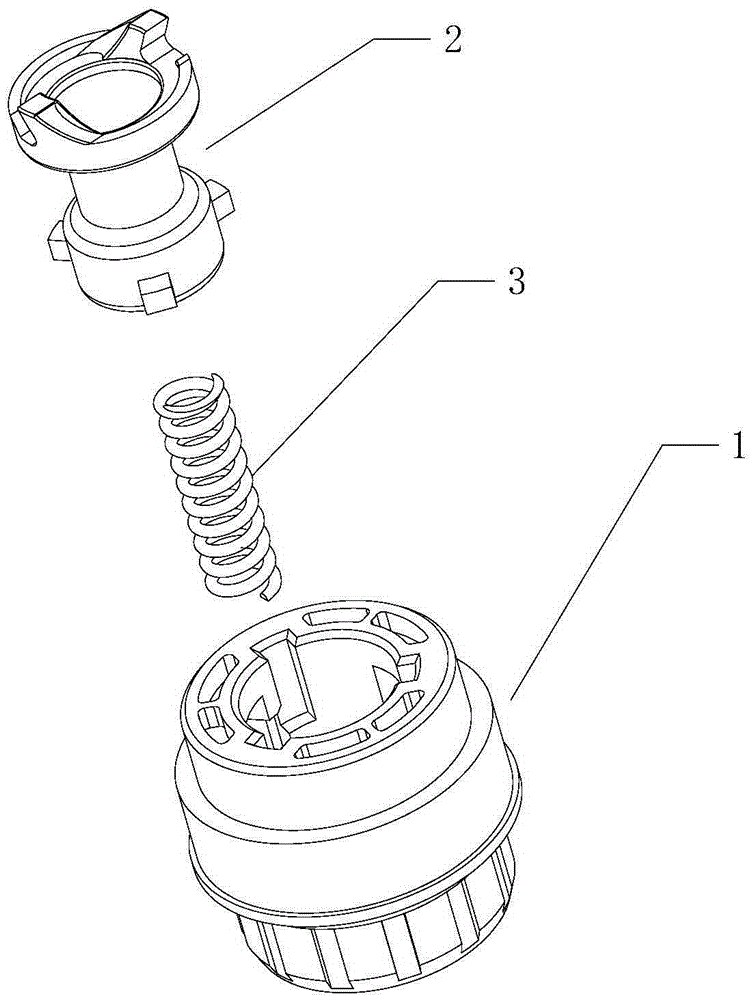
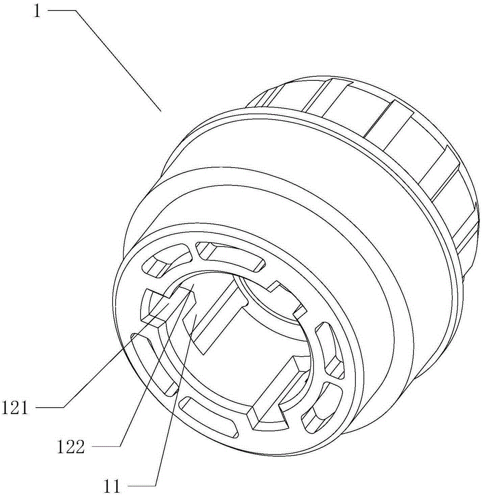
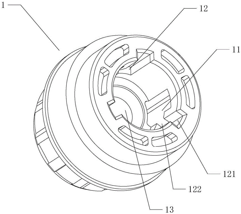
[0061] A photosensitive drum driving assembly, comprising a gear 1 cooperating with the photosensitive drum, a driving force receiving member 2 capable of receiving rotational driving force, a driving force receiving head 21 is arranged on the upper part of the driving force receiving member 2, and a driving force receiving head 21 is arranged on the lower part of the driving force receiving member 2 More than 3 protruding structures 22 protrude from the outer wall of the gear 1. The inner wall of the gear 1 is provided with more than 3 chute 11 along the axial direction of the gear 1. The upper end of the chute 11 is provided with a blocking structure. The side wall of the chute 11 is connected with The guide groove 12, the guide groove 12 communicates with the upper end of the gear 1 and the chute 11, each protruding structure 22 enters the chute 11 from the guide groove 12, and the protruding structures 22 are slidably arranged along the guide groove 12.

[0062] The protrud...

Embodiment 2

[0082] A photosensitive drum driving assembly, comprising a gear 1 cooperating with the photosensitive drum, a driving force receiving member 2 capable of receiving rotational driving force, a driving force receiving head 21 is arranged on the upper part of the driving force receiving member 2, and a driving force receiving head 21 is arranged on the lower part of the driving force receiving member 2 More than 3 protruding structures 22 protrude from the outer wall of the gear 1. The inner wall of the gear 1 is provided with more than 3 chute 11 along the axial direction of the gear 1. The upper end of the chute 11 is provided with a blocking structure. The side wall of the chute 11 is connected with The guide groove 12, the guide groove 12 communicates with the upper end of the gear 1 and the chute 11, each protruding structure 22 enters the chute 11 from the guide groove 12, and the protruding structures 22 are slidably arranged along the guide groove 12.

[0083] The protrud...


PUM


Abstract

The invention relates to a photosensitive drum drive component, which comprises a gear and a driving force receiving part, wherein the gear is matched with a photosensitive drum; the driving force receiving part can receive rotary driving force; a driving force receiving head is arranged at the upper part of the driving force receiving part; more than three bump structures extend outside on the outer wall of the lower part of the driving force receiving part; more than three sliding grooves are formed in the inner wall of the gear along the axis direction of the gear; a barrier structure is arranged at the upper end of each sliding groove; the side wall of each sliding groove is communicated with a guide groove; each guide groove is communicated with the upper end of the gear and each sliding chute; and the bump structures enter the sliding grooves from the guide grooves, and are arranged along the guide grooves in a sliding manner. The bump structures can slide in the sliding grooves, so that rotating transmission between the driving force receiving part and the gear structure is achieved; the driving force receiving part is not easily separated from the gear structure; the fault rate is low; and the stability is high. The invention further provides a processing box (a selenium drum) including the photosensitive drum drive component.

Description

technical field [0001] The invention relates to the technical field of printers, in particular to a photosensitive drum drive assembly and a toner cartridge containing the photosensitive drum drive assembly. Background technique [0002] A laser printer is a widely used printing and imaging device. A laser printer usually includes a paper feeding mechanism, a driving mechanism and a detachable toner cartridge (also known as a processing cartridge). The toner cartridge includes a powder bin and at least one rotating element, wherein the rotating element can be a developing element, a photosensitive element, a charging element or a transmission gear. One end of the rotating element is provided with a driving assembly, through which the connection with the driving mechanism is realized, and driven by the driving mechanism, the driving assembly drives the rotating element to rotate. Taking the photosensitive element as an example, under the driving action of the driving mechani...

Claims


Application Information

Patent Timeline
Patent Type & Authority Applications(China)
IPC IPC(8): G03G21/18
CPCG03G21/1821G03G15/757G03G21/1671
Inventor 肖文燚
Owner 新化凯尔影印科技有限公司
Why Eureka
Try Eureka