Wind-resistant stabilizing device for radar antenna array

A technology for stabilizing devices and radar antennas, applied in the direction of antenna supports/installation devices, etc., can solve the problems of radar maneuverability, increase the weight of external windproof facilities, increase the difficulty of erection, etc., achieve low cost, simple structure, and easy stability sexual effect

Active Publication Date: 2016-03-16
HARBIN INST OF TECH
View PDF3 Cites 3 Cited by
  • Summary
  • Abstract
  • Description
  • Claims
  • Application Information

AI Technical Summary

Problems solved by technology

The windshield can force the wind direction to change or the wind speed to decrease, but has a greater impact on radar maneuverability
(3) The addition of sealing wings increases the weight of the external windproof facilities and increases the difficulty of erection

Method used


Image

  • Wind-resistant stabilizing device for radar antenna array
  • Wind-resistant stabilizing device for radar antenna array

Examples


specific Embodiment approach 1

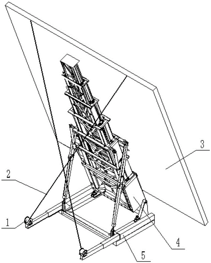
[0022] Combine below figure 1 , 2 This embodiment is described. The present invention relates to the technical field of military radar, more specifically, a radar antenna front wind resistance stabilization device. The radar antenna front wind resistance stabilization device includes a hoist 1, a steel wire rope 2 and an antenna front 3.

[0023] One end of the wire rope 2 is connected to the winch 1 , and the other end of the wire rope 2 is connected to the top of the antenna array 3 . The winch 1 is installed on the supporting platform 5 through bolts, the antenna array 3 is connected with the lifting tower 4, and the lifting tower 4 is installed on the supporting platform 5.

specific Embodiment approach 2

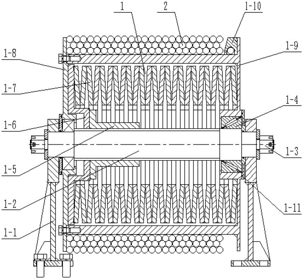
[0024] Combine below figure 1 , 2 To illustrate this embodiment, the winch 1 described in this embodiment includes a bracket 1-1, a ball screw 1-2, a slotted nut 1-3, a bearing 1-4, a ball nut 1-5, a floating plate 1-6, Disc spring 1-7, left reel cover 1-8, right reel cover 1-9, fixed block 1-10 and side sealing plate 1-11, the two ends of described ball screw 1-2 are respectively installed There is a bracket 1-1 and a bearing 1-4, the bracket 1-1 is located on the outside of the bearing 1-4, the bracket 1-1 is flexibly connected with the ball screw 1-2, the inner ring of the bearing 1-4 is connected with the ball screw The bars 1-2 are connected in an interference fit manner. The slotted nut 1-3 is arranged on the ball screw 1-2, and the slotted nut 1-3 is located on the outside of the ball screw 1-2, so as to avoid the gap between the bracket 1-1 and the ball screw 1-2. break away. The ball nut 1-5 and the floating plate 1-6 are all set on the ball screw 1-2, the ball nu...

specific Embodiment approach 3

[0027] Combine below figure 1 , 2 To illustrate this embodiment, the fixed block 1-10 described in this embodiment is provided with a rope threading hole; the steel wire rope 2 passes through the small hole in the fixed block 1-10, which can realize the contact with the radar in the process of ascent and descent. The angle of the antenna front 3 is fixed, so that the direction of the force remains unchanged, which is convenient for maintaining stability and prolonging the service life.


PUM


Abstract

The invention relates to the technical field of military radar, more specifically to a wind-resistant stabilizing device for a radar antenna array. One end of a steel wire rope is connected to a winch, and the other end of the steel wire rope is connected to the top end of the antenna array. Two ends of a ball screw are respectively provided with a support and a bearing, a slotted nut is arranged on the ball screw, a ball nut and a floating plate are both sleeved on the ball screw, and a disc spring is sleeved on the ball screw, the ball nut and the floating plate. A left drum cover is arranged at the left bearing, a right drum cover is arranged at the right bearing, and the left drum cover is fixedly connected to the right drum cover. A fixed stop is fixedly connected to the right drum cover. Two side sealing plates are respectively fixedly connected to the left drum cover and the right drum cover. The radar antenna array is obliquely pulled by the steel wire rope, so that the wind load is effectively resisted, the wind resistance is improved, stability is guaranteed, and the device is simple in structure and low in cost.

Description

technical field [0001] The invention relates to the technical field of military radar, in particular to a radar antenna front wind resistance stabilization device. Background technique [0002] In practical applications, in addition to the static and inertial loads of ice and snow and its own weight, radar also has dynamic loads from wind. The windward area of ​​a large radar antenna is large, and the wind load is relatively large, so it is particularly important to ensure the stability of the radar antenna against wind. At present, in order to ensure the stability of the radar antenna front against wind loads in China, it is mainly realized by changing the structure of the antenna front and adding external windproof facilities. [0003] There are several ways to change the structure of the antenna front: (1) Reasonably select the material of the antenna front and the structural form and component shape of the supporting back frame. For example, use orifice plates, grids o...

Claims


Application Information

Patent Timeline
Patent Type & Authority Applications(China)
IPC IPC(8): H01Q1/12
CPCH01Q1/12
Inventor 彭高亮薛渊邴宇涵孙瑜
Owner HARBIN INST OF TECH
Why Eureka
Try Eureka