
Overlaying tool for rotor punching plate of permanent magnet motor

A rotor punching and stacking tooling technology, which is applied in electromechanical devices, manufacturing motor generators, manufacturing stator/rotor bodies, etc., can solve the inconvenience of installing and disassembling the central shaft tube, the inability to remove the motor rotor, and the impact on processing efficiency and other problems, to achieve the effect of convenient operation, improved processing efficiency, and improved lamination efficiency

Active Publication Date: 2016-03-16
江苏经纬轨道交通设备有限公司
View PDF5 Cites 3 Cited by
  • Summary
  • Abstract
  • Description
  • Claims
  • Application Information

AI Technical Summary

Problems solved by technology

However, this structure is not convenient for the installation and disassembly of the central shaft tube, and the compressed motor rotor cannot be quickly removed from the central shaft tube in time; Inconvenient, processing efficiency is affected

Method used


Image

  • Overlaying tool for rotor punching plate of permanent magnet motor
  • Overlaying tool for rotor punching plate of permanent magnet motor

Examples


Embodiment Construction

[0013] The preferred embodiments of the present invention will be described in detail below in conjunction with the accompanying drawings, so that the advantages and features of the present invention can be more easily understood by those skilled in the art, so as to define the protection scope of the present invention more clearly.

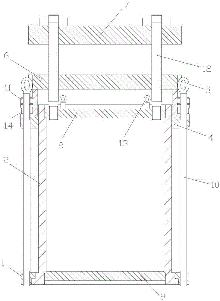
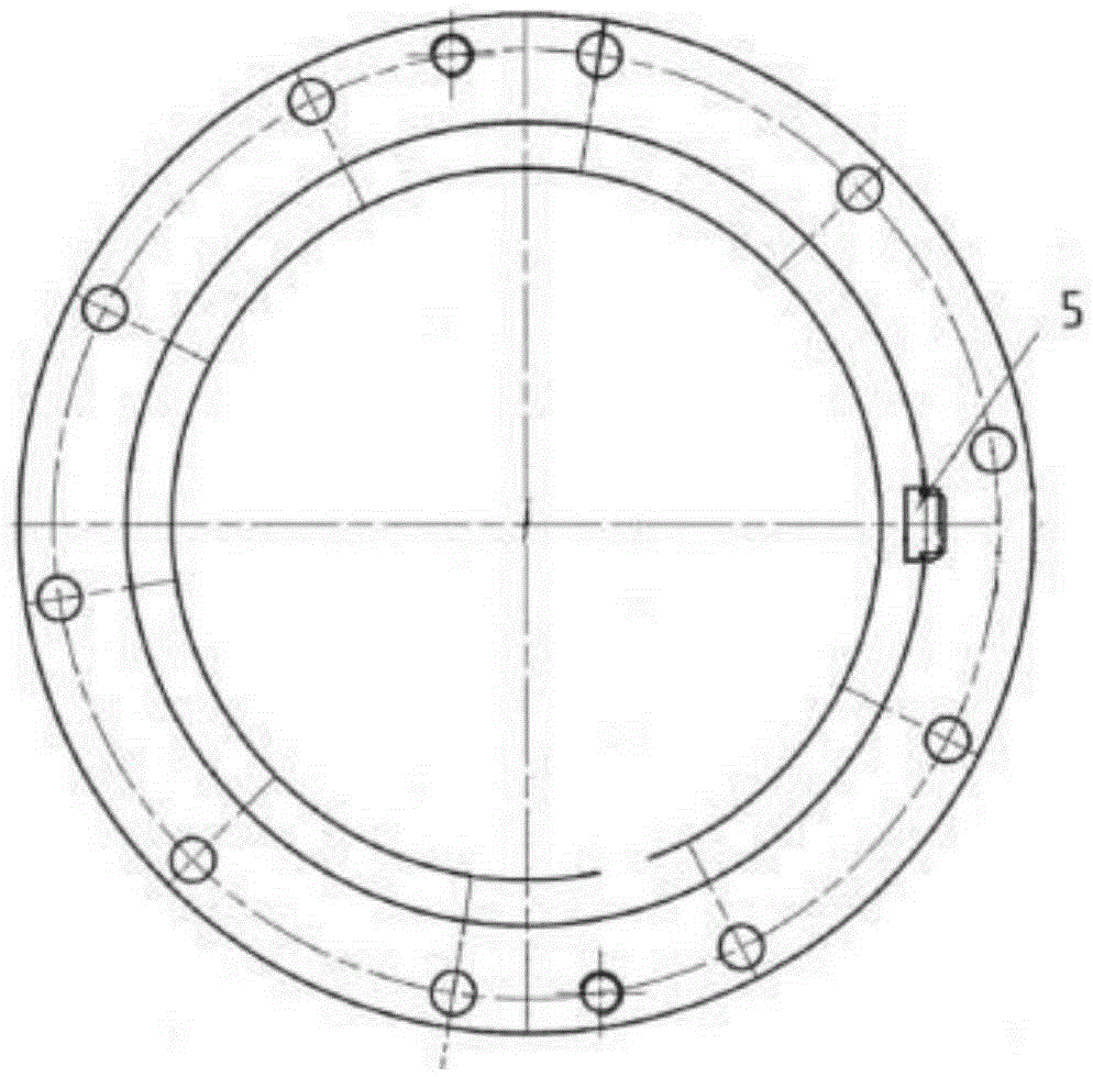
[0014] Please refer to the attached figure 1 and 2 , the embodiment of the present invention includes:

[0015] A permanent magnet motor rotor lamination lamination tooling, including a bottom plate 1, a central shaft cylinder 2, a flange plate, a pressure ring 4, a positioning rod 5, a pressure plate 6 and a press backing plate 7; the central shaft cylinder 2 is sequentially fitted with Bottom plate 1, pressure ring 4, pressure plate 6. The ports of the central shaft cylinder 2 are sealed with flange plates; the bottom plate 1 is fixed at one port of the central shaft cylinder 2 ; the pressure plate 6 is set on the other port of the central sh...


PUM


Abstract

The invention relates to an overlaying tool for a rotor punching plate of a permanent magnet motor. The overlaying tool comprises a bottom plate, a center beam barrel, flange plates, a compression ring, a positioning rod, a pressure plate and a press base plate; the bottom plate, the compression ring and the pressure plate sequentially sleeve the center beam barrel; the flange plates are packaged in both end ports of the center beam barrel; the bottom plate is fixed at one end port of the center beam barrel; the bottom plate is connected with the compression ring by fastening screws and fastening nuts; the pressure plate sleeves the other end port of the center beam barrel; the pressure plate acts on the compression ring and presses the compression ring to the bottom plate; connection screws are mounted on the press base plate; the connection screws pass through the pressure plate and are connected with the flange plate in the end port of the center beam barrel and inside the pressure plate; and the positioning rod for fixing the position of the rotor punching plate of the motor is also arranged between the center beam barrel and the compression ring.

Description

technical field [0001] The invention relates to a tooling for processing motor parts, in particular to a tooling for stamping and laminating the rotor of a permanent magnet motor. Background technique [0002] The motor rotor is the key component of the traction motor used in the subway. In order to prevent the eddy current loss on the surface of the rotor core caused by high-order harmonics, the surface of the motor rotor core is not processed, which requires improving the straightness of the rotor lamination process. and axis perpendicularity. In the past, the lamination of rotor punching was done manually. Manual lamination has high requirements on the operational skills required by workers. Moreover, the accuracy of manual lamination cannot meet the requirements for the use of the above-mentioned rotors. At the same time, manual lamination way, time-consuming and labor-intensive, and inefficient. For example, the Chinese invention patent "A Motor Rotor Punching and Lam...

Claims


Application Information

Patent Timeline
Patent Type & Authority Applications(China)
IPC IPC(8): H02K15/03
CPCH02K15/03
Inventor 张亚
Owner 江苏经纬轨道交通设备有限公司
Learn More