LED lamp circuit remotely controlled by wireless signal

A technology of LED lamp circuit and wireless signal, applied in the direction of lamp circuit layout, electric light source, electrical components, etc., can solve the problem of LED lamp not being intelligent, and achieve the effect of convenient transmission, circuit protection and prolonging service life.

Inactive Publication Date: 2016-03-16
WUHU RUIXIN ELECTRONICS TECH CO LTD
View PDF3 Cites 0 Cited by
  • Summary
  • Abstract
  • Description
  • Claims
  • Application Information

AI Technical Summary

Problems solved by technology

However, the current control of LED lights h

Method used


Image

  • LED lamp circuit remotely controlled by wireless signal
  • LED lamp circuit remotely controlled by wireless signal

Examples


Example Embodiment

[0014] Example:

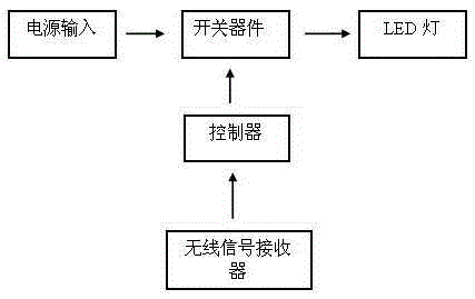
[0015] A wireless signal remote control LED lamp circuit, the wireless signal remote control LED lamp circuit includes a power input, a switch device, an LED lamp, a controller and a wireless signal receiver, the power input is connected in series to the switch device, and the switch device is connected in series to the LED lamp , the controller is connected to the switch device, and the wireless signal receiver is connected to the controller.

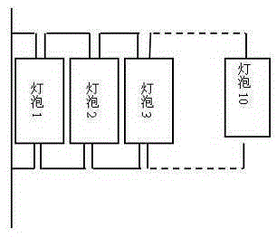
[0016] The switching device includes a switch and an automatic fuse, the power input includes a power plug and an electric shock prevention device, the LED light is composed of 20 bulbs connected in parallel, and the wireless signal receiver includes Bluetooth signal reception and wifi signal reception, The controller is set with a default operation, and when the input signal is wrong or unrecognizable, it will automatically default to open circuit.

[0017] The beneficial effects of adopting the above technical so...


PUM


Abstract

The invention discloses an LED (Light Emitting Diode) lamp circuit remotely controlled by a wireless signal. A switch device comprises a switch and an automatic fuse. When a circuit is in a short-circuit state, the automatic fuse can timely fuse the circuit to protect the safety of the circuit; and a power supply input part comprises a power supply plug and an electric-shock-protection device. Electric shock accidents occasionally occur when a user plugs the power supply plug. Therefore the electric-shock-protection device is additionally arranged on the power supply plug. The occurrence of the electric shock accidents can be effectively prevented; an LED lamp is formed by connecting ten bulbs in parallel; by using such a structure, the work among the bulbs is not mutually influenced, so that the service life of the LED lamp can be prolonged; a wireless signal receiver comprises a Bluetooth signal receiver and WiFi (Wireless Fidelity) signal receiver; the user can use different signal transmission modes according to difference distances; the transmission of the wireless signal is convenient; the controller has default operation; when the input signal is wrong or cannot be recognized, the circuit is automatically regarded as an open circuit state by default; and the circuit can achieve the circuit protection effect through the default setting.

Description

technical field [0001] The invention relates to the design field of various circuits used by LEDs, in particular to a wireless signal remote control LED lamp circuit. Background technique [0002] LED light is a kind of semiconductor diode, which can convert electrical energy into light energy. Like ordinary diodes, light-emitting diodes are composed of a PN junction and also have unidirectional conductivity. When a forward voltage is applied to the light-emitting diode, the holes injected from the P region to the N region and the electrons injected from the N region to the P region are respectively connected to the electrons in the N region and the vacancies in the P region within a few microns near the PN junction. Hole recombination, resulting in spontaneous emission of fluorescence. The energy states of electrons and holes are different in different semiconductor materials. The amount of energy released when electrons and holes recombine varies, and the more energy re...

Claims


Application Information

Patent Timeline
IPC IPC(8): H05B37/02
CPCH05B47/10
Inventor 崔俊国朱成华
Owner WUHU RUIXIN ELECTRONICS TECH CO LTD
Why Eureka
Try Eureka