
Perforating and embossing forming mold

A forming mold and hole pressing technology, which is applied in the fields of medical science, clothing, underwear, etc., can solve problems such as inability to guarantee synchronization, difficulty in achieving precise positioning, deviation of embossing and punching positions, etc., to improve alignment difficulties, Facilitate penetration and absorption, prevent side leakage and back leakage

Inactive Publication Date: 2016-03-23
XIAMEN YANJAN NEW MATERIAL CO LTD
View PDF7 Cites 5 Cited by
  • Summary
  • Abstract
  • Description
  • Claims
  • Application Information

AI Technical Summary

Problems solved by technology

However, at present, there are relatively few three-dimensional non-woven fabrics or films with both perforated and embossed structures. After the holes are punched in a punching machine, it is sent to the embossing roller for embossing. However, due to the certain distance between the machines, the non-woven fabric will deviate during the conveying process, so that the punched holes and the extruded The pattern can not be better aligned, resulting in unsightly appearance of the finished product
Although the invention patent CN201210066490.6 discloses a non-woven fabric punching machine, including convex tooth rollers, concave tooth rollers and embossing rollers, to achieve continuous production of punching and embossing, but because it is punched first and then Embossing cannot be guaranteed to be carried out at the same time. During the punching process, the position deviation of embossing and punching will also occur due to the stretching of the non-woven fabric. It is difficult to achieve precise positioning, and the three rollers are not easy to adjust and control, and the operation is complicated.

Method used

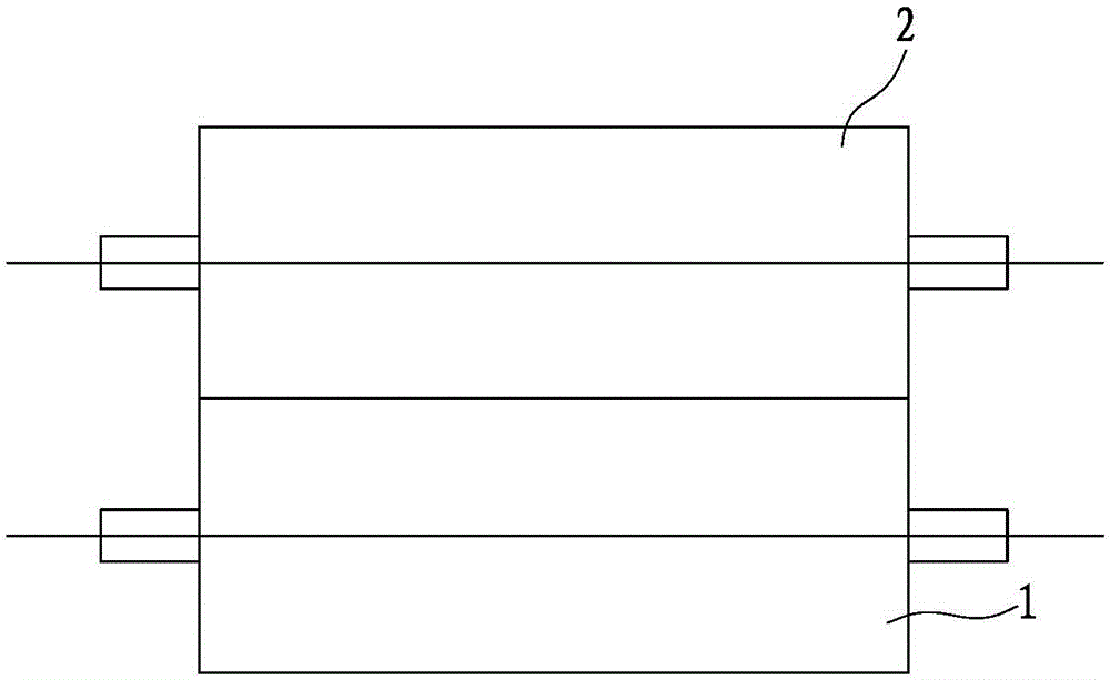
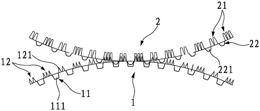
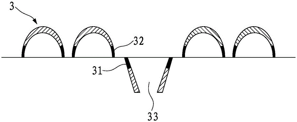

Image

  • Perforating and embossing forming mold
  • Perforating and embossing forming mold
  • Perforating and embossing forming mold

Examples


Embodiment 1

[0032] Such as Figure 4 , shown in 5, the punching and embossing molding die of the present invention comprises a convex roll 4 and a concave roll 5 that are engaged with each other, wherein the convex roll 4 has a perforated area 41 and a counterbore area 42, and the perforated area 41 Contains 1 tine, the bottom of the tine has a circular cross-section with an area of ​​3.14mm 2 , with a height of 3.0 mm, the counterbore area 42 includes a counterbore, the punched area 41 and the counterbore area 42 are spaced apart from each other; the concave roller 5 has a concave area 51 and a raised area 52, and the convex The raised area 52 includes a protrusion, the cross section of the bottom of the protrusion is circular, and the area is 7.07mm 2 , with a height of 3.5 mm, the concave hole area 51 corresponds to the perforated area 41 , and the raised area 52 corresponds to the counterbore area 42 . Both the convex roll 4 and the concave roll 5 are equipped with heating devices. ...

Embodiment 2

[0036] Such as Figure 6, shown in 7, the punching and embossing molding die of the present invention comprises a convex roller 6 and a concave roller 7 that are engaged with each other, wherein the convex roller 6 has perforated areas 61, 62 and counterbore areas 63, and the punched The hole areas 61, 62 include a plurality of tines of different needle shapes, and the cross section of the bottom of the tines in the tines area 61 is circular with an area of ​​3.14mm 2 , with a height of 3.0 mm, the cross-section of the bottom of the tine in the tine area 62 is circular, with an area of ​​1.13 mm 2 , with a height of 2.5 mm, the counterbore area 63 includes a dumbbell-shaped counterbore, the perforated areas 61, 62 and the counterbore area 63 are spaced apart from each other; the concave roller 7 has concave hole areas 71, 72 and protrusions Area 73, the raised area 73 includes a dumbbell-shaped protrusion, the cross-section of the raised bottom is dumbbell-shaped, the area is...

Embodiment 3

[0039] Such as Figure 8 , shown in 9, the punching and embossing molding die of the present invention comprises a convex roller 8 and a concave roller 9 that are engaged with each other, wherein the convex roller 8 has a perforated area 81 and a counterbore area 82, and the perforated area 81 contains a plurality of tines of the same needle shape, the cross-section of the bottom of the tines is circular, and the area is 2.01mm 2 , with a height of 2.5mm, the counterbore area 82 includes a plurality of counterbores, the perforated area 81 and the counterbore area 82 are spaced apart from each other; the concave roller 9 has a concave area 91 and a raised area 92, and the convex The raised area 92 comprises a plurality of protrusions, and the cross-section of the bottom of the protrusions is elliptical and has an area of ​​15 mm. 2 , with a height of 3.5 mm, the concave hole area 91 corresponds to the perforated area 81 , and the raised area 92 corresponds to the counterbore a...


PUM


Abstract

The invention discloses a perforating and embossing forming mold, which is composed of a concave and convex roller pair; the concave and convex rollers are mutually meshed, wherein perforating needle regions and counter bore regions, which are mutually spaced from each other, are arranged on the surface of the convex roller; convex regions and concave hole regions, which are mutually spaced from each other, are arranged on the surface of the concave roller; bumps on the concave roller correspond to concave holes on the convex roller; concave holes on the concave roller correspond to perforating needles on the convex roller; and both the convex roller and the concave roller are provided with heating devices. The forming mold disclosed by the invention achieves synchronous implementation of perforating and embossing and simplifies processing. A perforated and embossed product, which is produced by the perforating and embossing forming mold, has perforating and embossing regions, and the perforating and embossing regions are mutually spaced, so that a contact area with a human body is reduced through the distribution of the embossing regions, and meanwhile liquid infiltration is accelerated by virtue of the perforating regions; therefore, the forming mold is dyer and more comfortable.

Description

technical field [0001] The invention relates to a mold for punching and embossing non-woven fabrics and film rolls. Background technique [0002] Perforated and embossed non-woven fabrics or films are widely used in the fields of sanitary products and medical supplies, such as sanitary napkins, diapers, etc. The perforated and embossed three-dimensional non-woven fabrics or films have a three-dimensional structure, and the contact area with the skin Less, leading in the market. However, at present, there are relatively few three-dimensional non-woven fabrics or films with both perforated and embossed structures. After the holes are punched in a punching machine, it is sent to the embossing roller for embossing. However, due to the certain distance between the machines, the non-woven fabric will deviate during the conveying process, so that the punched holes and the extruded The patterns cannot be better aligned, resulting in an unattractive appearance after the finished pr...

Claims


Application Information

Patent Timeline
Patent Type & Authority Applications(China)
IPC IPC(8): A61F13/15
CPCA61F13/15577A61F13/15804A61F2013/15821
Inventor 谢继华蔡吉祥武丹聘罗杰龙
Owner XIAMEN YANJAN NEW MATERIAL CO LTD
Learn More