
High dispersion type vortex powder selecting machine

A technology of high dispersion and powder separator, which is applied in the direction of solid separation, separation of solids from solids by air flow, chemical instruments and methods, etc. It can solve the problem of unsatisfactory dispersion effect, uneven thickness of material curtain, and influence on powder selection. Efficiency and other issues, to achieve high classification accuracy, high powder selection efficiency, and improve the effect of powder selection efficiency

Inactive Publication Date: 2016-03-23
JIANGSU JINENGDA ENVIRONMENTAL ENERGY SCI & TECH
View PDF6 Cites 9 Cited by
  • Summary
  • Abstract
  • Description
  • Claims
  • Application Information

AI Technical Summary

Problems solved by technology

In the above-mentioned O-Sepa powder separator, the material entering from the top feed port is scattered to the surroundings through the spreading plate on the top of the cage-shaped rotor. In the powder selection area between the air guide vane and the rotor, the powder selection efficiency is low due to the uneven thickness of the material curtain falling between the guide vane and the rotor; The material is scattered, so the dispersion effect is not ideal and the coarse powder contains more fine powder, which affects the powder selection efficiency

Method used


Image

  • High dispersion type vortex powder selecting machine

Examples


Embodiment Construction

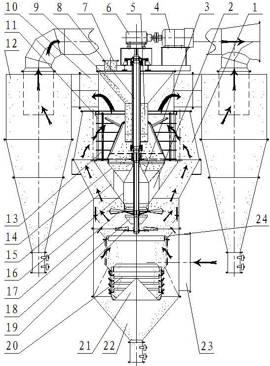
[0014] figure 1 Medium and high dispersion type eddy current powder separator, including shell 1, feeding pipe 7, coarse powder collecting cone 22, motor 4, reduction box 6, transmission shaft 8, spreading disc 17, guide vane 11, cage rotor 13. Both the motor 4 and the reduction box 6 are arranged on the top of the housing 1, and the motor 4 is connected to the reduction box 6. The upper end of the transmission shaft 8 is connected with the reduction box 6 , and the lower end of the transmission shaft 8 passes through the top of the housing 1 and is located in the housing 1 . The cage rotor 13 is arranged on the transmission shaft 8, and the spreading disc 17 is arranged on the transmission shaft 8 and is positioned under the cage rotor 13. The outer side of the cage rotor 13 is equipped with a circle of the guide blades 11, and the feed pipe 6 is arranged on the top of the housing 1, and the coarse powder collecting cone 22 is arranged on the lower end of the housing 1. The...


PUM


Abstract

The invention discloses a high dispersion type vortex powder selecting machine which comprises a shell, a feeding pipe, a coarse powder collection cone, a motor, a reduction box, a transmission shaft, a material scattering plate, guide fan blades and a cage rotor, and further comprises a cyclone dust collector, a feeding cone, a material dropping pipe, a material passing device, a lower material scattering plate and a cleaning device. The feeding cone is positioned in the shell; a lower opening of the feeding cone is connected with an upper opening of the material dropping pipe; the material passing device is positioned between the cage rotor and the material scattering plate, and is arranged on the inner wall of the shell; a material passing hole is formed in the center part of the material scattering plate; the lower material scattering plate is arranged at the lower end of the transmission shaft; an unloading cone is positioned between the material scattering plate and the lower material scattering plate, and is arranged on the inner wall of the shell; an air inlet pipe is arranged at the lower part of the shell; the cleaning device is positioned above the coarse powder collection cone, and is arranged on the inner wall of the shell; the cyclone dust collector comprises an air inlet, an air outlet and a feed outlet; an air outlet pipe is arranged on the side surface of the upper part of the shell; and the air outlet pipe is connected with the air inlet of the cyclone dust collector.

Description

technical field [0001] The invention relates to a powder separator, in particular to a highly dispersed eddy current powder separator. Background technique [0002] In the process of cement production, an O-Sepa powder classifier is used, which contains a shell with a cage-shaped rotor inside. , The top of the shell is provided with an air outlet pipe and a feed port, and the lower part of the rotor is a coarse powder cone. Working principle: The selected material enters from the feeding port on the top of the shell and falls on the rotating spreading plate. Due to the action of centrifugal force, the material is thrown out and hits the buffer plate to change direction and fall freely. A material curtain is formed in the annular space between them. The primary air and secondary air form 180 degrees from both sides of the shell 0 The two tangential air inlets enter, guided by the guide blades, and combined with the rotation of the rotor, a strong horizontal rotating flow s...

Claims


Application Information

Patent Timeline
IPC IPC(8): B07B9/02B07B7/01B07B7/083B07B11/00
CPCB07B9/02B07B7/01B07B7/083B07B11/00
Inventor 吕海峰曹海宁徐中州
Owner JIANGSU JINENGDA ENVIRONMENTAL ENERGY SCI & TECH
Learn More