L-shaped connection piece machining equipment

A technology for processing equipment and connectors, which is applied in the field of processing equipment for L-shaped connectors, can solve the problems of little increase in production efficiency, low production efficiency, and low processing accuracy, and achieve the effect of improving production efficiency

Inactive Publication Date: 2016-03-23
CHONGQING CHENGJISI MACHINERY MFG CO LTD
View PDF10 Cites 3 Cited by
  • Summary
  • Abstract
  • Description
  • Claims
  • Application Information

AI Technical Summary

Problems solved by technology

[0002] In the existing auto parts, connectors are an indispensable part, especially in the transport vehicles, a large number of connectors are used, especially L-shaped connectors are used at the connection between the carriage and the frame. The processing flow of the shaped connector is divided into blanking, bending, and drilling in turn; according to this process, each workpiece must be bent one by one, because the size of the connection is not large, and the tools of the bending machine are generally long, so When the bending machine is used to bend the L-shaped connector, the nature of the bending machine is fully utilized, resulting in a waste of resources, and because this process needs to bend each workpiece one by one, the production efficiency is not high
If the long material is placed first, that is, the length of the material is the sum of the lengths of multiple L-shaped connectors, and then the long material is bent, so that the bending of multiple L-shaped connectors can be completed at one time. Cut off the long material, and finally drill holes to improve the utilization rate of the bending mechanism. However, when cutting the long material, in order to ensure the length of the L-shaped connector, it is necessary to draw a line on the workpiece, so that the production efficiency is not improved. In addition, due to the long length of the material, when cutting, it is difficult to fix and the vibration is large, so that the processing accuracy is not high

Method used


Image

  • L-shaped connection piece machining equipment
  • L-shaped connection piece machining equipment

Examples


Embodiment Construction

[0013] The present invention will be described in further detail below by means of specific embodiments:

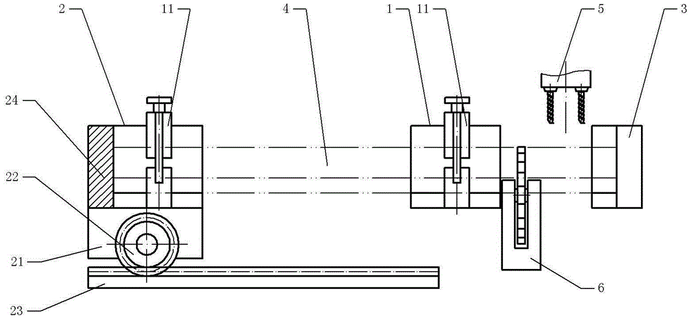
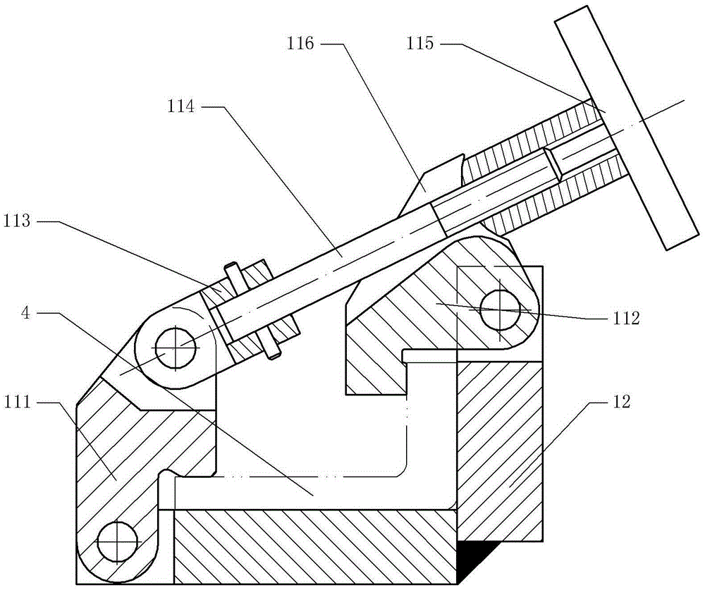
[0014] The reference signs in the drawings of the specification include: clamping part 1, pushing part 2, limit seat 3, workpiece 4, drilling part 5, cutting part 6, clamping mechanism 11, base 12, jaw one 111 , Jaw two 112, connection seat 113, linkage lever 114, handle 115, groove 116, mounting seat 21, gear 22, rack 23, limit plate 24.

[0015] The embodiment is basically as attached figure 1 , figure 2 As shown: the L-shaped connector processing equipment includes a frame, a clamping part 1, a pushing part 2, a drilling part 5, and a cutting part 6; as shown in the figure, the clamping part 1 includes a base 12 and a clamping mechanism 11; Clamping mechanism 11 comprises jaw one 111, jaw two 112, linkage rod 114 and handle 115; Respectively hinged on the two flanges of the base 12, the jaw one 111 is also hinged with a connecting seat 113, the connecting seat 113 ...


PUM


Abstract

The invention discloses L-shaped connection piece machining equipment, and relates to the machining equipment. The L-shaped connection piece machining equipment comprises a machine frame, a drilling portion and a cutting portion and further comprises clamping portions and a push portion. Each clamping portion comprises a base and a clamping mechanism. The section of each base is in an L shape. Each clamping mechanism comprises a first clamping jaw and a second clamping jaw which are hinged to the corresponding base and further comprises a linkage rod and a handle. The bases are fixed to the machine frame. One end of each linkage rod is hinged to the corresponding first clamping jaw. A groove is formed in the corresponding second clamping jaw. The linkage rods are embedded into the corresponding grooves. A workpiece can be clamped and located in two directions by screwing the handles. The push portion comprises a mounting seat, a rack and a gear. The mounting seat is connected to the rack in a sliding manner. The gear is rotationally connected to the mounting seat. The rack is fixed to the machine frame. The gear is meshed with the rack and driven by a drive motor to rotate so that the push portion can push the workpiece to be jacked and pressed to a limiting seat, and the workpiece is located in the axial direction.

Description

technical field [0001] The invention relates to a mechanical processing equipment, in particular to an L-shaped connector processing equipment. Background technique [0002] In the existing auto parts, connectors are an indispensable part, especially in the transport vehicles, a large number of connectors are used, especially L-shaped connectors are used at the connection between the carriage and the frame. The processing flow of the shaped connector is divided into blanking, bending, and drilling in turn; according to this process, each workpiece must be bent one by one, because the size of the connection is not large, and the tools of the bending machine are generally long, so When the bending machine is used to bend the L-shaped connector, the nature of the bending machine is fully utilized, resulting in a waste of resources, and because this process needs to bend each workpiece one by one, the production efficiency is not high. If the long material is placed first, that...

Claims


Application Information

Patent Timeline
Patent Type & Authority Applications(China)
IPC IPC(8): B23P23/02B23Q3/06
CPCB23P23/02B23Q3/062
Inventor 陈勇
Owner CHONGQING CHENGJISI MACHINERY MFG CO LTD
Why Eureka
Try Eureka