
Auger conveying mechanism for dust or particle material storage and transportation container

An auger conveying mechanism and granular material technology, which is applied in the field of storage and transportation containers, can solve the problems of energy consumption and unsatisfactory work, and achieve the effect of energy saving and energy saving

Active Publication Date: 2016-03-23
NENGCHENG GRP
View PDF6 Cites 1 Cited by
  • Summary
  • Abstract
  • Description
  • Claims
  • Application Information

AI Technical Summary

Problems solved by technology

However, when this type of auger conveying mechanism needs to unload the material, the material at the end far away from the auger outlet will be emptied first, and the other parts of the material will not be discharged obviously. This is because: in the screw of the auger When the rod is rotating, the material entering the spiral groove from the end of the screw rod away from the outlet of the auger moves along the spiral groove toward the outlet; since this part of the material always occupies the spiral groove, the material close to the outlet can hardly enter the spiral groove again. That is to say, the material relatively close to the outlet of the auger can only be unloaded after the material farther away from the outlet of the auger is unloaded; Large pressure, turning these pressures into resistance will consume a lot of energy, and such resistance is constantly changing with the discharge of materials, which also makes the driving source of the screw rod work in an unideal working condition for a long time

Method used


Image

  • Auger conveying mechanism for dust or particle material storage and transportation container
  • Auger conveying mechanism for dust or particle material storage and transportation container
  • Auger conveying mechanism for dust or particle material storage and transportation container

Examples


Embodiment 1

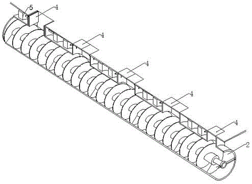
[0042] Such as figure 1 and 2 As shown, the auger conveying mechanism of the dust or granular material storage and transportation container described in this embodiment includes a conveying trough 2 arranged at the bottom of the storage and transportation container, an auger assembly arranged in the conveying trough 2, and the The storage and transportation container is connected with the conveying tank 2 with a plurality of communication holes 3 arranged in rows, wherein the arrangement direction of the communication holes 3 is consistent with the transport direction of the auger assembly, and each communication hole 3 is provided with at least one cover plate 4, and the cover plate 4 can close or open the strip groove or the communication hole 3 under the action of the control assembly; wherein, preferably a plurality of the communication holes 3 along the The transportation direction of the auger assembly is evenly distributed, and two cover plates 4 are arranged in each ...

Embodiment 2

[0055] As a changeable implementation of embodiment 1, such as figure 1 and 3 As shown, the auger conveying mechanism of the dust or granular material storage and transportation container described in this embodiment includes a conveying trough 2 arranged at the bottom of the storage and transportation container, an auger assembly arranged in the conveying trough 2, and the The storage and transportation container is connected with the delivery tank 2, wherein the length direction of the strip slot is consistent with the transport direction of the auger assembly, and at least one cover is provided on the strip slot plate 4, the cover plate 4 can close or open the strip-shaped groove or the communication hole 3 under the action of the control assembly; wherein, in this embodiment, the length of the strip-shaped groove is the same as that of the conveying groove 2 have the same length. In this way, in the actual operation process, the cover plate 4 close to the discharge port...


PUM


Abstract

The invention discloses an auger conveying mechanism for a dust or particle material storage and transportation container. The auger conveying mechanism for the dust or particle material storage and transportation container comprises a conveying groove formed in the bottom of the storage and transportation container, an auger assembly arranged in the conveying groove, and a strip-shaped groove or a plurality of communication holes, wherein the storage and transportation container and the conveying groove are communicated through the stripe-shaped groove or the communication holes, and the communication holes are formed in rows. The length direction of the strip-shaped groove or the arrangement direction of the communication holes is consistent with the conveying direction of the auger assembly. The strip-shaped groove or each communication hole is provided with at least one cover plate. The strip-shaped groove or the communication holes can be closed or opened through the cover plates under the control of control assemblies. In this way, in an actual operation process, the cover plate close to a discharge outlet can be closed, and the cover plate away from the discharge outlet can be opened, so that the situation that when materials at the end away from the discharge outlet are discharged firstly, materials at the end close to the discharge outlet apply pressure to the auger assembly through the strip-shaped groove or the communication holes, and accordingly certain resistance is caused to the movement of the auger assembly is avoided; the conveying efficiency of the auger assembly is improved, and energy resources are saved.

Description

technical field [0001] The invention relates to a storage and transportation container for storing and transporting dust or granular materials, in particular to an auger conveying mechanism for the storage and transportation container of dust or granular materials. Background technique [0002] The auger conveying mechanism is a common conveying device for conveying dust or granular materials. For containers storing such materials, if the auger conveying mechanism is arranged at the bottom of the container along the length direction of the auger, and the auger is fed through a long through hole or a series of alternately arranged through holes along the length direction of the auger. The conveying pipe communicates with the inner cavity of the storage and transportation container. As disclosed in Chinese patent document CN101164850A, a new type of cement tank with controllable discharge includes a tank body and a screw conveyor at the bottom of the tank body. One end of the...

Claims


Application Information

Patent Timeline
Patent Type & Authority Applications(China)
IPC IPC(8): B65G65/46B65G33/14B65G33/26B65G33/34B65G33/32B65G33/24
Inventor 王斌坚
Owner NENGCHENG GRP
Learn More