
Equipment for averagely distributing separated ore pulp

A technology for equal distribution and pulp distribution, applied in liquid distribution, distribution devices, special distribution devices, etc., can solve the problems of few pulp equalization devices, low pulp distribution efficiency, and inability to achieve equal distribution effects, achieving strong practicability, preventing Clogging, high efficiency effect

Inactive Publication Date: 2016-03-23
吴振宇
View PDF4 Cites 4 Cited by
  • Summary
  • Abstract
  • Description
  • Claims
  • Application Information

AI Technical Summary

Problems solved by technology

[0003] There are very few existing slurry equalizing devices. The Chinese patent No. 201420538958.1 discloses a slurry distribution device, which includes a slurry feeding pipe, an inner barrel, an outer barrel, a slurry discharge pipe, a movable ring and a steady flow grid; First enter the inner barrel, the inner barrel overflows into the outer barrel, and then distribute the ore pulp through the slurry discharge pipe on the outer barrel; although this device can satisfy the distribution of ore pulp, it cannot achieve a good even distribution effect. In addition, because the ore pulp needs to First enter the inner barrel, and then enter the outer barrel, the distribution efficiency of the pulp is very low

Method used


Image

  • Equipment for averagely distributing separated ore pulp
  • Equipment for averagely distributing separated ore pulp

Examples


Embodiment 1

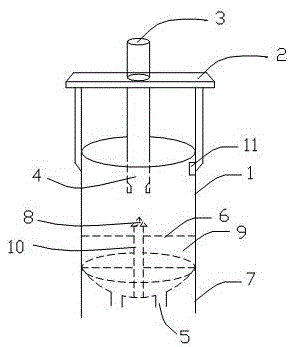
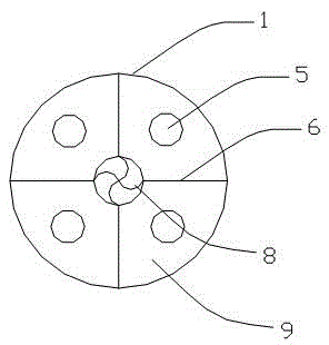
[0023] like Figure 1~2 As shown, this embodiment is a device for evenly distributing ore dressing pulp, including a pulp inlet pipe 3, a bucket rack 2, a slurry bucket 1, a necking funnel 4, a slurry separation head 8, a slurry separation column 10, and a liquid level detection device 11 And the pulp outlet pipe 5, wherein, the barrel upper frame 2 is located above the pulp barrel 1, and is fixedly connected with the barrel wall of the pulp barrel 1, one end of the pulp inlet pipe 3 is fixedly connected to the barrel upper frame 2, and the other end is suspended vertically on the pulp barrel 1, and is located on the vertical center line of the pulp tank 1, the outlet of the pulp inlet pipe 3 communicates with the necking funnel 4, and the pulp enters the pulp tank 1 from the necking funnel 4, and the slurry separating column 10 is set at the center of the bottom wall of the pulp tank 1 At the position, the slurry head 8 is arranged on the top of the slurry column 10, and is r...


PUM


Abstract

The invention discloses equipment for averagely distributing separated ore pulp. The equipment comprises a pulp inlet pipe, a barrel upper frame, a pulp barrel, a necking funnel, a pulp separating head, a pulp separating column, a liquid level detecting device and pulp outlet pipes; the barrel upper frame is fixedly connected above the pulp barrel; one end of the pulp inlet pipe is fixedly connected to the barrel upper frame, and the other end of the pulp inlet pipe is vertically suspended in the pulp barrel; an outlet of the pulp inlet pipe is communicated with the necking funnel; the pulp separating column is arranged in the center of the bottom wall of the pulp barrel; the pulp separating head is arranged at the top end of the pulp separating column, and is rotationally connected relative to the pulp separating column; the pulp outlet pipes are uniformly distributed on the bottom wall of the pulp barrel; the section of the bottom wall of the pulp barrel is arched; ore pulp flows out of the necking funnel; the pulp separating head automatically rotates under the impact of the ore pulp to disperse the ore pulp; the ore pulp uniformly drops to the lower part of the pulp barrel; as the section of the bottom wall of the pulp barrel is arched, the stop of the ore pulp at the bottom of the pulp barrel is prevented; one end of the pulp inlet pipe is fixedly connected to the barrel upper frame to prevent the shaking of the pulp inlet pipe; and the device can uniformly distribute the ore pulp without needing any driving device, and is high in efficiency and high in practicability.

Description

technical field [0001] The invention relates to the technical field of mineral processing equipment, in particular to a device for evenly distributing ore dressing pulp. Background technique [0002] In the field of mineral processing, during the production process, it is often necessary to divide the ore pulp into several parallel operating equipment in the same process. In production, the uneven ore supply and concentration of each equipment often affect the performance of the equipment and operating efficiency. How to divide the ore pulp It is a problem to be solved that the amount and concentration are given to all the equipment in the next process as evenly as possible. [0003] There are very few existing slurry equalizing devices, and the Chinese patent No. 201420538958.1 discloses a slurry distribution device, which includes a slurry feeding pipe, an inner barrel, an outer barrel, a slurry discharge pipe, a movable ring and a steady flow grid; First enter the inner ...

Claims


Application Information

Patent Timeline
Patent Type & Authority Applications(China)
IPC IPC(8): B67D3/00
CPCB67D3/00
Inventor 吴振宇
Owner 吴振宇
Learn More