Hydraulic system of fast injection circuit of die casting machine

A technology of hydraulic system and die-casting machine, applied in mechanical equipment, fluid pressure actuating device, servo motor, etc., can solve the problems of pressure oil pressure reduction, energy waste, oil heating, etc., to ensure speed requirements and reduce pressure loss , the effect of simple and reasonable structure

Active Publication Date: 2017-08-04
广东联升精密智能装备科技有限公司
View PDF9 Cites 0 Cited by
  • Summary
  • Abstract
  • Description
  • Claims
  • Application Information

AI Technical Summary

Problems solved by technology

The existing rapid injection circuit of the die casting machine is a single circuit, that is, the first-stage rapid injection circuit and the second-stage rapid injection circuit share an accumulator, and the first-stage rapid injection circuit is used to push the metal liquid to be filled to the inside. The gate has lower requirements on speed, the resistance to be overcome is small, and only needs a small energy storage pressure, while the second injection speed is used to fill the cavity with molten metal through the ingate, which requires a lot of speed. High, to overcome greater resistance, a higher energy storage pressure is required, so the accumulator requires a higher energy storage pressure, because the pressure required for the first-stage fast injection is small, and the energy storage pressure of the accumulator Higher, resulting in excessive pressure loss of the first-stage rapid injection, resulting in waste of energy, the lost energy makes the oil heat, and because part of the pressure oil in the accumulator is used for the first-stage rapid injection, the energy storage The pressure oil pressure of the device is reduced, which is not conducive to ensuring the speed requirement of the second stage of fast injection

Method used


Image

  • Hydraulic system of fast injection circuit of die casting machine
  • Hydraulic system of fast injection circuit of die casting machine

Examples


Embodiment Construction

[0015] The present invention will be further described below in conjunction with the accompanying drawings and embodiments.

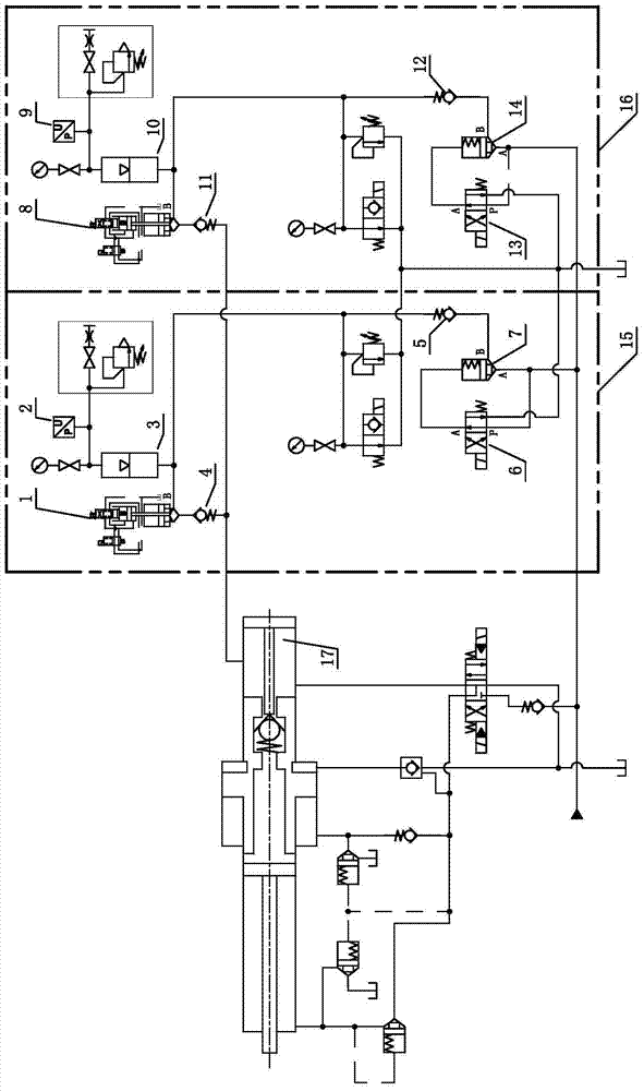
[0016] see figure 1 , the hydraulic system of the fast injection circuit of the die-casting machine, including the injection cylinder, and the first-stage rapid injection circuit 15 and the second-stage rapid injection circuit 16 which are independent of each other and connected in parallel; the first-stage rapid injection circuit 15 and the two ends of the second-stage fast injection circuit 16 are respectively connected to the rear cavity 17 of the injection cylinder. The first-stage rapid injection circuit 15 and the second-stage rapid injection circuit 16 are connected in parallel to ensure mutual non-interference during operation. The first-stage fast injection circuit 15 does not consume the pressure oil of the accumulator b 10, which ensures that the pressure of the accumulator b 10 does not drop, saves energy, and in turn helps to ensure the sp...


PUM


Abstract

The invention relates to a hydraulic system with fast injection loops of a die casting machine. The hydraulic system comprises an injection oil cylinder, a first stage of fast injection loop and a second stage of fast injection loop, wherein the first stage of fast injection loop and the second stage of fast injection loop are mutually independent and connected with each other in parallel, and the connected two ends of the first stage of fast injection loop and the second stage of fast injection loop are respectively connected with the rear chambers of the injection oil cylinder. Each of the first stage of fast injection loop and the second stage of fast injection loop uses an independent accumulator, and the first stage of fast injection loop and the second stage of fast injection loop are not interfere with each other in the working process. The pressure loss of the first stage of fast injection is reduced, and energy is saved. The first stage of fast injection does not consume the pressure oil of the second stage of fast injection accumulator, so that the pressure of the second stage of fast injection accumulator is not reduced, and therefore the speed demand of the second stage of fast injection can be beneficially ensured. The hydraulic system has the characteristics of being simple and reasonable in structure and energy-saving and being beneficial to ensuring the speed demand of the second stage of fast injection.

Description

technical field [0001] The invention belongs to the field of die-casting machinery and equipment, and in particular relates to a hydraulic system of a fast injection circuit of a die-casting machine. Background technique [0002] The injection performance of the die-casting machine is one of the main factors affecting the quality of the die-casting parts. When paying attention to the quality of die castings, the requirements for energy saving and consumption reduction of die casting machines are getting higher and higher. The existing rapid injection circuit of the die casting machine is a single circuit, that is, the first-stage rapid injection circuit and the second-stage rapid injection circuit share an accumulator, and the first-stage rapid injection circuit is used to push the metal liquid to be filled to the inside. The gate has lower requirements on speed, the resistance to be overcome is small, and only needs a small energy storage pressure, while the second injecti...

Claims


Application Information

Patent Timeline
Patent Type & Authority Patents(China)
IPC IPC(8): F15B1/04F15B11/08
CPCF15B1/04F15B11/08
Inventor 覃展敏彭新上万介荣
Owner 广东联升精密智能装备科技有限公司
Why Eureka
Try Eureka