
Flow limiting valve

A valve and current limiting technology, which is applied in the direction of fluid flow, fluid pressure actuators, servo motor components, etc., can solve the problems that cannot be effectively controlled by the system with extremely small flow, and achieve low cost of use, not easy to block, and good economy Effect

Inactive Publication Date: 2016-03-23
SHENYANG AIRCRAFT DESIGN INST AVIATION IND CORP OF CHINA
View PDF9 Cites 2 Cited by
  • Summary
  • Abstract
  • Description
  • Claims
  • Application Information

AI Technical Summary

Problems solved by technology

[0003] The purpose of the present invention is to provide a flow limiting valve to solve the problem in the background art that it cannot effectively control the system with extremely small flow

Method used


Image

  • Flow limiting valve
  • Flow limiting valve
  • Flow limiting valve

Examples


Embodiment Construction

[0022] In order to make the objectives, technical solutions and advantages of the present invention clearer, the technical solutions in the embodiments of the present invention will be described in more detail below in conjunction with the drawings in the embodiments of the present invention. In the drawings, the same or similar reference numerals denote the same or similar elements or elements having the same or similar functions throughout. The described embodiments are some, but not all, embodiments of the invention. The embodiments described below by referring to the figures are exemplary and are intended to explain the present invention and should not be construed as limiting the present invention. Based on the embodiments of the present invention, all other embodiments obtained by persons of ordinary skill in the art without creative efforts fall within the protection scope of the present invention. Embodiments of the present invention will be described in detail below ...


PUM


Abstract

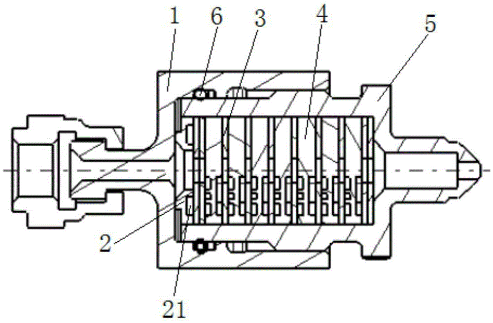
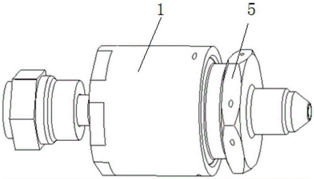
The invention discloses a flow limiting valve and relates to the technical field of hydraulic pressure. The flow limiting valve comprises an end cover, a plurality of gaskets, flow limiting pieces and a shell. A first through hole is formed in each gasket. Vortex grooves are formed in the two sides of each flow limiting piece, and the vortex grooves in the two sides of each flow limiting piece are communicated. The gaskets are arranged on the two sides of the flow limiting piece, and the vortex grooves are communicated with the first through holes. The shell is provided with a containing cavity. The gaskets and the flow limiting pieces are placed in the containing cavity. The shell is sleeved with the end cover, and the end cover is fixedly connected with the shell and tightly presses the gaskets and the flow limiting pieces in the axial direction. The flow limiting valve has the advantages that the vortex grooves are formed in the flow limiting pieces, liquid passes through the vortex grooves to form vortexes, the flow speed of the liquid is decreased, multiple flow limiting pieces can be arranged according to the flow control requirements, and the effective control over the extremely small flow is achieved.

Description

technical field [0001] The invention relates to the technical field of hydraulic systems, in particular to a flow limiting valve. Background technique [0002] The flow limiting valve is a flow control accessory commonly used in the hydraulic system, mainly used to control the movement speed of the hydraulic actuation system. The two-way flow limiting valves currently used in the market mainly use the small hole throttling technology to adjust the flow rate of hydraulic oil through the change of the hole diameter. The system forms an effective control. Contents of the invention [0003] The purpose of the present invention is to provide a flow limiting valve to solve the problem in the background art that it cannot effectively control the system with extremely small flow. [0004] The technical solution of the present invention is to provide a flow limiting valve comprising an end cover, a plurality of gaskets, a flow limiting piece and a housing, wherein the gasket is p...

Claims


Application Information

Patent Timeline
Patent Type & Authority Applications(China)
IPC IPC(8): F15B13/02F15D1/00
CPCF15B13/02F15B2013/008F15D1/009
Inventor 王德奇王连江于永鹏范锐吴鹏飞
Owner SHENYANG AIRCRAFT DESIGN INST AVIATION IND CORP OF CHINA
Learn More